PCM Software Manual1997 Viper · SR · 8.0L V10 · JTEC PCM
1997 Viper · SR · 8.0L V10 · JTEC PCM

PCM Software Manual

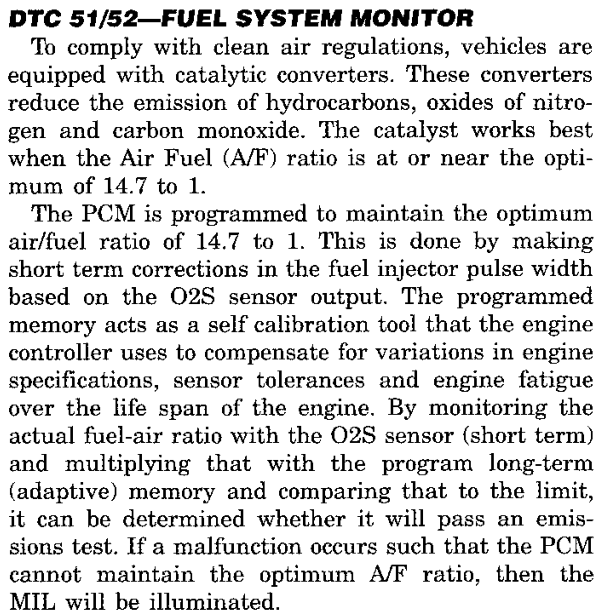
Calibration 04848703AF · reference image SHA-256 82c2832024feae3d5427df4baddbaedcc80cdd0958e3e33155f4b78e1c21c2c0

GROUP INDEX

Interactive page

HOW TO USE THIS MANUAL. Each group follows the order of a factory service manual: Description and Operation, Diagnosis and Testing, Specifications. Calibration structures appear in the group that uses them and, complete, in Group 9. Routine addresses such as 018588 and ROM addresses such as 3D65 refer to the reference image; select one to open its entry.

SR0 · INTRODUCTION0 - 1

ABOUT THIS MANUAL

DESCRIPTION AND OPERATION

PURPOSE AND SCOPE

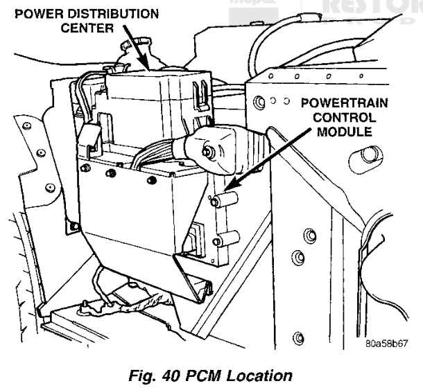
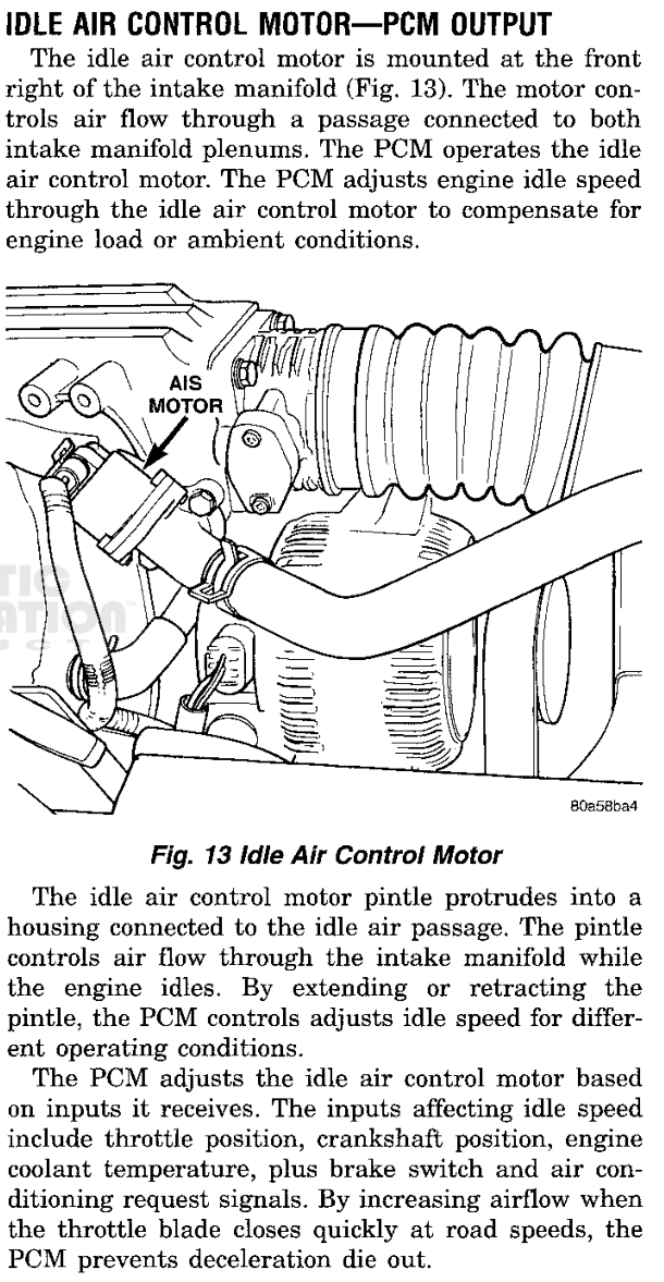
This manual describes the software of the 1997 Viper SR powertrain control module (PCM). It covers the 8.0L V10 engine and the JTEC controller. The PCM is a digital computer containing a microprocessor, mounted underhood next to the heater motor blower housing (Fig. 1). It reads its inputs, makes its control decisions, and operates its outputs as described in the service manual. This manual explains the program that makes those decisions.

Every statement in this manual is taken from one reference image, the 256 KiB flash image VIP_2A03.ori, with calibration 04848703AF. The image is identified in 0-2 Reference Image Identification. The processor is a Motorola 68HC16. The image occupies CPU addresses 000000 through 03FFFF. Where this manual describes vehicle wiring, connectors, or component operation, it follows the 1997 Dodge Viper Service Manual and identifies the service manual group.

The manual describes what the software does with its inputs, flags, requests, tables and output commands. It does not replace the service manual for vehicle-side diagnosis and repair.

The PCM mounted underhood beside the power distribution center
Fig. 1 PCM Location (Group 14)

HOW THIS MANUAL IS ORGANIZED

The manual is divided into groups in the same way as the service manual. Group 0 introduces the manual, identifies the reference image, and defines terms (0-3 Glossary). Group 1 describes how the program starts, schedules its work and handles interrupts (1-2 Startup and Initialization, 1-3 Job Scheduling, 1-4 Interrupts). Groups 2 through 8 describe individual systems: engine events, fuel, ignition, outputs, speed and transmission, sensor fault handling, and on-board diagnostics.

Each system section is arranged in the service manual order:

PARTCONTENTS
Description and OperationThe routines, signals and calibration values that make up the function, with flowcharts and listings
Diagnosis and TestingDRB output tests and trouble codes that use the function, where they exist
SpecificationsCalibration values read from the reference image, and PCM connector circuits

A table of the calibration structures used by the section closes each system section. Group 9 holds the calibration data: the flash structure of the complete image (9-1 Flash Structure) and every calibration table, curve, setting and record, grouped by system. Group 10 is the reference group. It holds the PCM connector pinouts (10-1 PCM Connector Pinouts), the work schedule tables (10-2 Work Schedule Tables), the routine index (10-3 Routine Index) and the alphabetical index (10-4 Alphabetical Index).

ROUTINE, RAM AND ROM ADDRESSES

A routine is named by the six-digit hexadecimal address of its first instruction, for example the A/C clutch control routine 018588. Each routine address in the text is a link to its entry in the routine index, which gives the routine name and every section that refers to it. Section 5-2 Accessory and Evaporative Outputs describes this routine in full.

Working values are held in RAM at addresses F8000 and above. At reset, the initialization routine (020000) selects bank F and loads the Z index register with 8000 (Fig. 2). Instructions written as an offset from Z therefore address F8000 plus the offset: LDAA 0x5a,Z reads F805A. The manual always gives the full five-digit RAM address.

RESET INITIALIZATION · 020000RAM base
020000LDAB  #0xf; bank F020002TBZK  ; Z bank02000ALDZ   #0x8000; Z = F8000
Fig. 2 RAM Base Selected at Reset

RAM from F8000 through F87FF is cleared at every reset. RAM from F8800 upward holds retained values. The reset routine preserves them when their stored check sum matches, and seeds default values when it does not (1-2 Startup and Initialization).

A single bit is written with its mask value in hexadecimal. "F8107, bit 20" is the bit tested and set by #0x20 in the byte at F8107.

Calibration values are read from ROM by their four-digit address, for example 3D65. In a listing a ROM operand is written without an index register: CMPA 0x3d65 compares the accumulator with the calibration byte at 3D65 (Fig. 3). Each calibration value printed in this manual is read from the reference image when the manual is built, and its raw value is shown when the pointer rests on it.

A/C CLUTCH CONTROL · 018588reading a listing
0186DALDAA  0x5a,Z; RAM F805A, engine speed0186F0CMPA  0x3d65; ROM 3D650186F6BSET  0x674,Z,#0x20; RAM F8674, bit 200186FCLDAA  0xa6,Z; RAM F80A6, coolant018712CMPA  0x3d67; ROM 3D67018718BSET  0x674,Z,#0x10; RAM F8674, bit 10
Fig. 3 RAM Signals and ROM Calibration in a Listing

FIGURES AND FLOWCHARTS

Figures are numbered within each section. Four kinds of figure are used:

  • Flowcharts show the order of decisions in a function. Shaded cards mark the request, flag or command that the function produces. A card that carries a routine address links to that routine.
  • Listings reproduce the decisive instructions of a routine from the reference image, with the instruction address at the left and a comment at the right. Readable C listings show the same logic in C. Each one is checked against the original instructions.
  • Calibration figures draw a table as a heat map or a curve, with its ROM address and the routine that reads it. Each one links to its complete entry in Group 9.
  • Service manual figures are reproduced from the 1997 Dodge Viper Service Manual. The caption gives the service manual group.

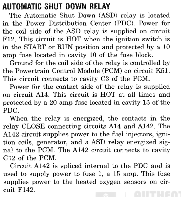
The three kinds of reference meet in each system section (Fig. 4). A routine reads RAM signals and ROM calibration and produces a request. An output command carries the request to a PCM circuit, and the service manual figure shows that circuit in the vehicle.

RAM SIGNALF805A · F80A6ROUTINE018588 · group 10-3CALIBRATIONROM 3D65 · group 9REQUEST OR FLAGF8107 · bit 20OUTPUT COMMANDgroup 5VEHICLE CIRCUITservice manual figure · group 10-1
Fig. 4 How References Relate

REVISIONS

This manual is revised as more of the PCM software is documented in readable C. Sections gain listings, flowcharts and calibration figures with each revision. Every revision is built from the same reference image. The build checks the image, every routine address, every listing address and every printed calibration value, so a page that disagrees with the image is not published.

SPECIFICATIONS

CONVERSIONS

The PCM stores values as raw counts. The manual prints them in physical units with the conversions below. A value with no conversion is printed in hexadecimal.

QUANTITYSTORED ASCONVERSIONEXAMPLE
Engine speed, wordF805A wordword ÷ 8 = rpm—
Engine speed, byteF805A high byte, ROM limitscount × 32 = rpmROM 3D65 = 5632 rpm
Coolant temperatureF80A6, ROM limitscount − 64 = °CROM 3D67 = 121 °C
Unconverted byteROMhexadecimalROM 3DE3 = DA
Timer reload or countROM worddecimal countsROM 3D5B = 91 counts

ADDRESS RANGES

RANGECONTENTSREFER TO
000000–03FFFFFlash image: program, calibration and diagnostic data9-1 Flash Structure
F8000–F87FFWorking RAM, cleared at every reset1-2 Startup and Initialization
F8800–F8A04Retained RAM, kept while its check sum matches1-2 Startup and Initialization
ENGINE SPEED AXIScurve
608 → 0704 → 16800 → 32896 → 48992 → 641152 → 801344 → 961632 → 1122016 → 1282400 → 1442816 → 1603360 → 1763904 → 1924448 → 2085024 → 2245600 → 2406176 → 255Engine speed 608–6176 RPMOutput 0–255 raw counts
Points (17)
ENGINE SPEED (RPM)OUTPUT (RAW COUNTS)
6080
70416
80032
89648
99264
115280
134496
1632112
2016128
2400144
2816160
3360176
3904192
4448208
5024224
5600240
6176255

ROM 002814–002836 · 35 bytes · Read by 0109DC, 011B14

Fig. 5 Engine Speed Axis — breakpoints convert at 32 rpm per count — complete entry 9-7, Fig. 4
0 - 20 · INTRODUCTIONSR

REFERENCE IMAGE IDENTIFICATION

DESCRIPTION AND OPERATION

REFERENCE IMAGE

This manual describes one PCM program: the reference image VIP_2A03, a 262,144-byte (256 KiB) copy of the main processor flash memory. Every routine address, table address and calibration value in this manual is an offset into that image. The build of this manual checks the SHA-256 hash of the image before it reads any value, so every figure and specification is taken from the same bytes. Refer to Specifications.

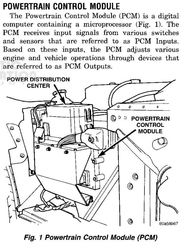
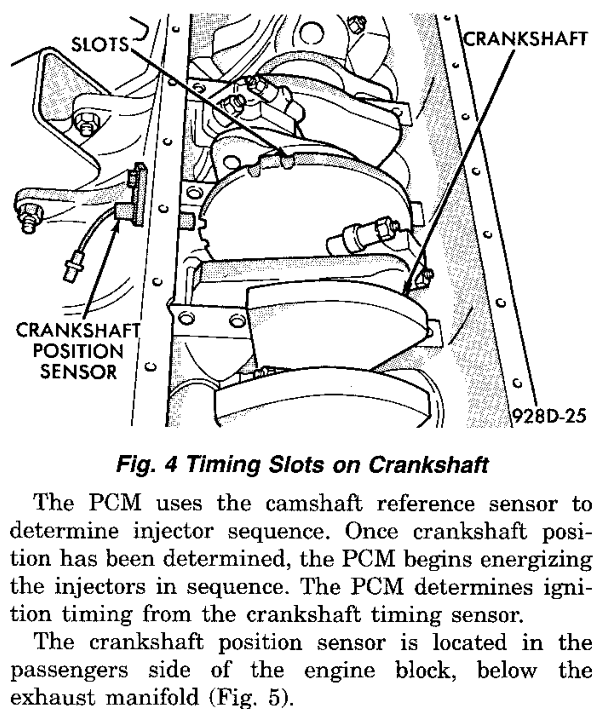
The PCM is a digital computer containing a microprocessor (Fig. 1). In this image the main processor is a Motorola CPU16-family (68HC16) device. The program uses the CPU16 20-bit address space: the bank registers extend 16-bit addresses, program code runs in banks 0 through 2, and RAM and the on-chip modules sit in bank F. The serial communications interface (SCI) status and data registers, for example, are read and written at FFC0C and FFC0E.

Service manual text describing the PCM as a digital computer containing a microprocessor, with Fig. 1 showing the PCM beside the power distribution center
Fig. 1 Powertrain Control Module (Group 14)

CALIBRATION IDENTIFICATION

The image carries calibration number 04848703AF. The long word at 000200 points to the identifier at 002738. The identifier is six bytes: four bytes of packed BCD (0484 8703) followed by the ASCII revision letters 41 and 46 ("AF"). A second copy of the same six bytes begins at 00273F (Fig. 3).

Chrysler's scan-tool flash catalog lists 04848703AF for the 1997 SR 8.0L BUX application (Built Up Export, the export Viper). It supersedes calibrations 04848703AA, AB, AC, AD and AE and is released under TSB 18-24-98. The domestic 1997 application carries a different calibration number (04848702).

The PCM reports its identification through the SCI diagnostic service (00C800). Request 2A selects the identification lookup at 00DF22. The request carries a one-based index from 1 to 31. The routine selects one of two address lists by a state byte in RAM: the list at F741 when the byte holds 55, otherwise the list at F703. It loads the indexed address, reads that byte of the image and sends it with the SCI transmit routine (00EBC0), which waits for the transmitter-empty flag before it writes the data register (Fig. 2). The leading entries of the F703 list address the first identifier copy; those of the F741 list address the second.

SCI DIAGNOSTIC SERVICE · 00C800request 2A
00DF22CLRB  00DF24TBXK  00DF26LDAB  0x346,Z; requested index00DF2ALBEQ  0x00ebd6; zero: finish00DF2EDECB  00DF30CMPB  #0x1f; index limit00DF32LBGE  0x00ebd600DF36LDAA  0x35a,Z; list select state00DF3ACMPA  #0x5500DF3CBEQ   0x00df4800DF3ELDX   #0xf703; first list00DF42ABX   00DF44ABX   00DF46BRA   0x00df5000DF48LDX   #0xf741; second list00DF4CABX   00DF4EABX   00DF50LDX   0x0,X; address from list00DF52LDAB  0x0,X; identification byte00DF54JSR   0x00ebc0; transmit00DF58JMP   0x00ebd6
Fig. 2 Identification Byte Lookup
CALIBRATION IDENTIFIER AND DUPLICATErecords
BYTE OFFSETSTORED BYTE
+004
+01132
+02135
+033
+0465
+0570
+06160
+074
+08132
+09135
+0A3
+0B65

2 more records in 9-6, Fig. 13

ROM 002738–002745 · 14 bytes

Fig. 3 Calibration Identifier and Duplicate — complete entry 9-6, Fig. 13

ENGINE PROFILE SELECTION

The image holds engine profiles for several engine configurations. The calibration selects one of them at startup. The reset initialization routine (020000) reads the engine profile selector at 002707 and compares it with eight single-bit values. In this image the selector is 02, and the branch at 0204CA selects the V10 profile at 0006CA and the output-mask table at 0008BA (Fig. 5). The routine stores both pointers in RAM (F8058 and F8177). Engine routines read the profile through the stored pointer from then on, so no other profile takes part in operation. Refer to 1-2 Startup and Initialization.

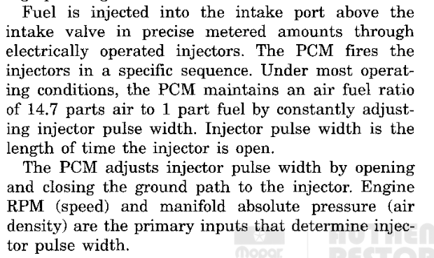
The selected profile records a cylinder count of 10 at 0006CB and again at 000702. The firing-order sequence at 0006E4 lists cylinders zero-based. Adding one to each entry gives 1-10-9-4-3-6-5-8-7-2, the firing order of the 8.0L V10 engine (Fig. 6). Two more copies follow at 0006EE and 0006F8, each rotated one position further. The cylinder-indexed accumulator routine (0119EE) reads the copy at 0006F8 through the profile pointer, selected by profile byte 0006D3 (02), and the engine event interrupt (028F24) uses the cylinder count to form its cylinder-position index. The output-mask table holds ten distinct single-bit masks. The fuel pulse-width routine (0109DC) and the startup fuel routine (011B14) read it through the stored mask pointer. Refer to 2-1 Engine Position and Timing.

02otherRESET VECTOR000000 · PK 1 · PC 0000JUMP TABLE ENTRY010000 · JMP 020000RESET INITIALIZATIONbank registers · stack · modulesSELECTOR = 02 ?ROM 002707V10 PROFILEprofile 06CA · masks 08BACALIBRATIONselector 2707OTHER PROFILESseven selector bits
Fig. 4 Reset and Engine Profile Selection
RESET INITIALIZATION · 020000profile selector
020436LDAA  0x2707; engine selector020442CMPA  #0x80020444BNE   0x02045a02045ACMPA  #0x40020472CMPA  #0x20020488CMPA  #0x1002049ECMPA  #0x80204B4CMPA  #0x40204CACMPA  #0x2; V10 selector0204CCBNE   0x0204e00204CELDX   #0x6ca; V10 profile0204D2LDY   #0x8ba; output masks0204DEBRA   0x0204f40204F4STX   0x58,Z; profile pointer0204F8STY   0x177,Z; mask pointer
Fig. 5 Engine Profile Selection
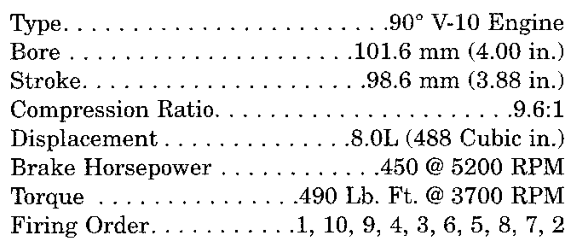
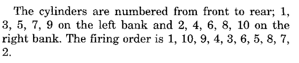
Engine specification list: 90 degree V-10, 8.0L, 450 horsepower at 5200 rpm, firing order 1, 10, 9, 4, 3, 6, 5, 8, 7, 2
Fig. 6 8.0L V10 Engine Specifications (Group 9)
V10 FIRING-ORDER SEQUENCErecords
POSITIONSTORED CYLINDER INDEXCYLINDER NUMBER
001
1910
289
334
423
556
645
778
867
912

ROM 0006E4–0006ED · 10 bytes

Fig. 7 V10 Firing-Order Sequence — complete entry 9-6, Fig. 4

MEMORY MAP

The image begins with the CPU16 reset vector. Its four words set the initial bank registers, program counter, stack pointer and IZ register. The program counter word 0000 with program bank 1 starts execution at 010000, the first entry of a 27-entry jump table, which jumps to the reset initialization routine at 020000. The 252 interrupt vector words from 000008 to 0001FF follow. All but one point to short jump stubs in bank 0; vectors without a handler point to the default fault stub 00081E, which jumps to the default trap entry 02194A. The SCI vector (4E, at 00009C) points directly to the SCI transmit interrupt routine (00EC5A). The vector table is drawn in 1-4, Fig. 2; refer to 1-4 Interrupts.

Calibration and configuration data occupy the low 64 KiB, separated by FF fill. The principal calibration area runs from 002600 to 003F9F and holds the engine selector and the identifier. The SCI diagnostic service and its protocol tables sit between 00C800 and 00FC01. The main program begins at 010000 and ends at 02A00F; a copyright record follows, and FF fill runs from 02A02A to the end of the image. The table below lists the principal regions. Refer to 9-1 Flash Structure for the block-by-block map.

ADDRESS RANGECONTENT
000000–000007Reset vector: initial ZK/SK/PK, PC, SP and IZ
000008–0001FFInterrupt vectors (252 words)
000200–000203Calibration identifier pointer (to 002738)
000402–000855Interrupt and fault jump stubs, with sensor conversion, schedule and engine-profile data between them
000934–000D33Logical EEPROM address mapping
001000–0014F2Configuration and diagnostic code records
002600–003F9FPrincipal calibration area: engine selector, identifier, fuel and spark tables
006000–00826EConstants, lookup tables and condition lists
009000–0094D2Transmission diagnostic calibration
00A000–00A509Transmission control curves and scalars
00C000–00C47CComponent header ("COPYRIGHT 1991-1996 CHRYSLER"), diagnostic monitor descriptors and handler pointers
00C800–00ECC1SCI diagnostic service
00ECC2–00FC01Diagnostic protocol tables, including the identification address lists
010000–02A00FMain program, beginning with the 27-entry jump table
02A010–02A029Copyright record ("COPYRIGHT 1994 CHRYSLER")
02A02A–03FFFFFF fill

SPECIFICATIONS

DESCRIPTIONSPECIFICATIONROM
Image nameVIP_2A03—
Image length262,144 bytes (256 KiB)000000–03FFFF
SHA-25682c2832024feae3d5427df4baddbaedcc80cdd0958e3e33155f4b78e1c21c2c0—
Calibration number04848703AF2738, 273F
Application1997 Viper SR 8.0L V10, BUX (export)—
Service bulletinTSB 18-24-98—
Engine profile selector02 (V10)2707
Selected profile / output masks06CA / 08BA0204CE
Cylinder count1006CB
Firing order1-10-9-4-3-6-5-8-7-206E4
Reset vector, bank word (ZK/SK/PK)0FF10000
Reset vector, program counter00000002
Reset vector, stack pointer87FE0004
Reset vector, IZ80000006
Identifier pointer27380200

The calibration number is four bytes of packed BCD followed by two ASCII letters. Application and bulletin are from Chrysler's scan-tool flash catalog.

CIRCUITPCM CAVITYFUNCTION
D21C1-27SCI transmit (PCM perspective)
D20C1-29SCI receive (PCM perspective)
SR0 · INTRODUCTION0 - 3

GLOSSARY

TERMS

Active fallback flag
Working state that helps select a substitute input now. It can clear while a trouble code remains stored.
Calibration / map
Saved numbers or tables used to make control decisions, such as a starting fuel amount.
Cylinder bank
One group of cylinders on one side of a V-shaped engine.
Cylinder bank
One of the engine’s two cylinder groups. Bank-specific codes distinguish the group being monitored.
ECU / PCM
The engine computer. PCM is Chrysler's name for the powertrain control module.
Evaporative purge
Control associated with moving stored fuel vapors into the engine.
Fault trap
A path for an unexpected processor condition. These handlers do not return to the normal work in this image.
Flag
A small saved yes/no state, such as whether a calculation is requested.
Fuel trim
A fuel correction made using feedback. Short-term correction reacts to recent readings; long-term correction remembers an adjustment over time.
Fuel-inhibit mask
A set of selection bits that can tell the fuel calculation to hold back a prepared pulse for particular logical cylinders. Why each bit is set still needs tracing.
Held reading
A previous working value kept while the current sample is rejected. It can be stale.
Immediate-invalid flag
A software note that a local input check rejected a sample. The complete fault-code policy is a separate process.
Input capture
Hardware that remembers the timer value when an electrical edge arrives, so software can measure when it happened.
Internal fault id
An index used inside the program to select a diagnostic record. It is different from the reported OBD number and the legacy blink-code byte.
Interrupt
A signal that asks the processor to pause what it is doing and handle an event.
Interrupt service routine (ISR)
A small entry path that responds when the processor is interrupted. It may do work itself or ask the scheduler to do more.
Monitor qualification
Conditions and remembered observations that determine whether a diagnostic check may run and whether a result should be recorded.
P-number / trouble code
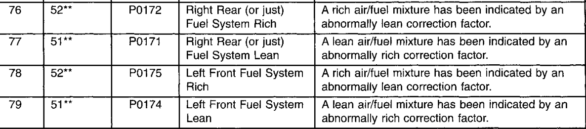
A diagnostic reporting code such as P0171. P means powertrain. The code identifies a condition the controller can report; it does not by itself identify a failed part.
Qualifying observation
A check result accepted after the relevant gates. It is not automatically a fixed amount of time or one driving trip.
Rich and lean
Rich means too much fuel relative to air. Lean means too little fuel relative to air.
ROM / flash image
A saved copy of program and calibration memory. It is not a recording of a running car.
Scheduler
The part of the program that chooses which ready job gets a turn.
SCI
A serial communication link used for diagnostic requests and responses.
Software-tracked position
A position the program remembers from its own requests. Without a traced feedback sensor, it is not proof of the actual mechanical position.
Stale reading
A saved value that has not received a fresh sample within the program’s allowed count. Its fallback value need not describe what the car is actually doing.
Substituted reading
A replacement value chosen from another signal, a stored value or an estimate. It is not a fresh measurement of the failed input.
Tick
One count of the scheduler's timebase.
Watchdog
A check that notices when expected activity has not happened. This program has checks for engine events and a separate processor watchdog.
Watchdog countdown
A value refreshed by expected activity and checked later. If the activity stops, an expiry path can change the software state. Here its unit is a check visit, not a confirmed number of seconds.
SR1 · SYSTEM OVERVIEW1 - 1

SYSTEM OVERVIEW

DESCRIPTION AND OPERATION

PCM SOFTWARE STRUCTURE

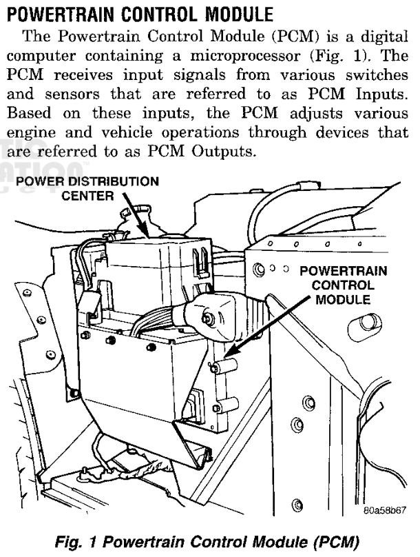
The Powertrain Control Module (PCM) is a digital computer containing a microprocessor. It receives input signals from switches and sensors and adjusts engine and vehicle operation through its outputs (Fig. 2). This manual describes the software in the PCM main processor of the 1997 Viper SR 8.0L V10, calibration 04848703AF.

The software does not run a single repeating list of engine calculations. After reset it initializes the hardware and settles in a one-instruction idle branch. All recurring work begins in interrupts. A periodic interrupt collects sensor readings and counts scheduler ticks; an engine-event interrupt records engine-position timing and flags each event. The periodic interrupt then carries the work through one chain of services: engine-speed calculation, engine-control dispatch (fuel and spark), serial and vehicle-speed service, and finally the job scheduler that runs the periodic jobs (Fig. 1).

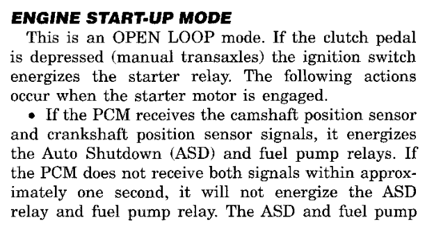
The PCM selects its responses from preset programming and its current operating state, which the service manual calls the modes of operation (Fig. 3). In the software, those modes are flags and phase states that the engine-speed service and the scheduled jobs set, and that the fuel, spark and output routines read.

Fig. 1 Main Software Paths
Powertrain Control Module description and location beside the power distribution center
Fig. 2 Powertrain Control Module (Group 14)

The manual follows the same order as the software. Each group below covers one stage of the paths in Fig. 1.

GROUPSUBJECTBEGIN WITH
0Identification of the reference image, terms0-2 Reference Image Identification
1Reset, interrupts, scheduler and periodic jobs1-2 Startup and Initialization
2Engine position, engine speed and event loss2-1 Engine Position and Timing
3Fuel amount and oxygen-sensor feedback3-1 Fuel Amount
4Spark timing4-1 Spark Timing
5Output commands and accessory outputs5-1 Output Commands
6Vehicle speed, transmission controls, reverse lockout6-1 Vehicle Speed Input
7Sensor substitute values and recovery7-1 Substitute Values
8Diagnostics, fault reporting, blink codes8-1 Diagnostic Overview
9Calibration tables and records9-1 Flash Structure
10Pinouts, schedules, routine and subject indexes10-1 PCM Connector Pinouts
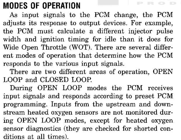
Modes of operation: the PCM adjusts its response to output devices as inputs change, with open loop and closed loop areas of operation
Fig. 3 Modes of Operation (Group 14)

RESET AND FOREGROUND IDLE

The reset routine (020000) sets the bank registers, the stack and the common RAM base, then configures the chip selects, RAM mapping, analog converter, timer and serial modules. It loads the three periodic-group countdowns from the descriptors listed at ROM 0464 and reads the engine profile selector at ROM 2707. The value 02 selects the V10 engine profile at ROM 06CA and the ten fuel-output masks at ROM 08BA. Startup also queues the initial commands for the output hardware. Refer to 1-2 Startup and Initialization.

The reset routine lowers the interrupt mask at 0206AA, so interrupts are serviced during the remainder of startup. Near its end it writes 55 and then AA to the watchdog service register. Its final instruction jumps to the foreground idle branch (028500), a single branch to itself. The idle branch does not service the watchdog; the first job of the fastest periodic group (01FC58) does.

INTERRUPT-DRIVEN WORK

The periodic interrupt (028502) stores the analog converter results, services timer capture and overflow, updates vehicle-speed state and restarts conversion. Different sensor channels are processed on different visits. The interrupt then accounts for one scheduler tick (1-3, Fig. 1, 1-3 Job Scheduling). When engine-event maintenance is already running, the tick is added to the accumulated count F8006 and the interrupt returns. When the scheduler is active, the tick is accumulated for the scheduler to consume. Otherwise the countdown service (028906) decrements each group countdown directly and marks expired groups ready.

The engine-event interrupt (028F24) captures the event timestamps, updates synchronization history and profile state, reloads the engine-event watchdogs and sets work-pending flags. At and above the calibrated engine speed at ROM 2138, and with F80BC bit 40 set, it also sends the prepared fuel value of the bank selected by F80BC bit 20 (F82B0 or F82B2) directly to the output hardware. Refer to 2-1 Engine Position and Timing.

When the engine-event interrupt has captured an event, the periodic interrupt calls the engine-speed service (026CFC). It consumes the timestamp history, calculates engine speed F805A, updates the startup and running phase flags, and sets engine-control pending bits in F80D2. The dispatcher (028992) takes the lowest set bit, clears it, and calls the handler listed for it at ROM 0478 (1-3, Fig. 3, 1-3, Fig. 4). It repeats until no pending bit remains. The phase flags decide whether the startup or the running fuel and spark routines are requested.

BITHANDLERWORK
010109DCRunning fuel (3-1 Fuel Amount)
0201015ARunning spark (4-1 Spark Timing)
04016A36Engine interval history
08011B14Startup fuel
100100E8Spark initialization, post-start mode
20–80—Return immediately

When the pending bits are clear, the speed and serial service (01E14E) services the output queue, vehicle speed and the SCI link. When the SCI receiver holds data, the service calls the diagnostic service (00C800). Refer to 6-1 Vehicle Speed Input and 8-1 Diagnostic Overview. The service then enters the job scheduler, unless the scheduler is already running (Fig. 4).

SPEED AND SERIAL SERVICE · 01E14Escheduler entry
01E2DEPULM  K,IZ,IX,E,D01E2E0BCLR  0xd1,Z,#0x4; maintenance done01E2E4BRCLR 0xce,Z,#0x2,0x01e2ee; scheduler active01E2EAJMP   0x010014; return01E2EEBSET  0xce,Z,#0x2; mark active01E2F2ANDP  #0xff2f01E2F6PSHM  IZ,K01E2F8JMP   0x010060; job scheduler
Fig. 4 Scheduler Entry

Two further interrupts operate alongside these paths. A level-5 interrupt (029F90) acknowledges its source and services the output queue. The SCI transmit interrupt (00EC5A) sends serial data from a table. The interrupt vectors are listed in 1-4, Fig. 2; refer to 1-4 Interrupts.

PERIODIC JOB SCHEDULING

Periodic jobs are organized in three groups, each a list of three-byte records: a job routine and its priority state. The scheduler (028B6A) scans the three group states and selects the ready group with the greatest priority. It runs one record of that group (028BB4), advances the group cursor, and scans again, so jobs of different groups interleave while each group keeps its listed order (1-3, Fig. 8). A record of FFFF ends a group. Ticks that arrive while a job runs are applied to the countdowns (028C4A) before the next scan. When no group is ready, the scheduler clears its active flag and returns from the interrupt.

A group that comes due while its previous release is still running is marked with state bit 80; it is not released twice. Within a group, many jobs run their full body only under their own conditions or subrates. Refer to 1-3 Job Scheduling, 1-5 Scheduled Jobs and 1-6 Supporting Jobs.

The fastest group carries the watchdog service, transmission dispatch and reverse lockout (6-2 Transmission Controls, 6-3 Reverse Lockout), coolant and intake-air filtering, deceleration and engine-speed cut requests, the changed discrete-output commands (029AFC), the engine-event watchdog expiry (013E3E), OBD requests, and the purge and oxygen-feedback jobs (5-2 Accessory and Evaporative Outputs, 3-2 Fuel Feedback). The slower groups carry fuel timers, transmission temperature, event-loss output state and fuel-cut profile countdowns.

OUTPUT HANDOFF AND FAULT RECORDS

The software sends its results to the output hardware as commands. The command queue (029270) holds them and the QSPI service (0293F6) transmits them. The running fuel routine stores bank results F82B0 and F82B2; the spark routine stores its final timing in F83D9 and queues spark command 24. Discrete requests in F8106 through F8108 are queued only when they change. Refer to 5-1 Output Commands.

When engine events stop, the event-watchdog expiry resets the engine-speed and phase state and enters the event-loss output path (2-2 Loss of Engine Events). Sensor faults substitute calibrated values (7-1 Substitute Values, 7-2 Sensor Recovery). Emission faults are stored as diagnostic trouble codes and are displayed by DRB or by blink code (8-2 Fault Reporting, 8-3 Blink Code Display, 8-4 Entering Blink Code Mode).

CPU exceptions use a separate path. The exception entries (0218C0 onward) record an internal fault byte at F8A06 and enter a port-write loop (021954). These internal codes are not diagnostic trouble codes.

SPECIFICATIONS

DESCRIPTIONSPECIFICATIONROM
Engine profile selector (V10)022707
Periodic groups3040E
Group 1 period22 ticks08DC
Group 2 period172 ticks08ED
Group 3 period1953 ticks090A
Engine-control handler table8 slots0478

Group periods count periodic-interrupt ticks. Group 1 holds 4 jobs, group 2 holds 8 and group 3 holds 12.

CALIBRATION STRUCTURES

STRUCTUREROMTYPEREFER TO
Calibration identifier and duplicate002738records9-6, Fig. 13
1 - 21 · SYSTEM OVERVIEWSR

STARTUP AND INITIALIZATION

DESCRIPTION AND OPERATION

RESET ENTRY AND PROCESSOR SETUP

Every reset of the PCM main processor enters the reset routine (020000). The routine runs once, from top to bottom, and prepares the processor, memory, engine profile and companion devices before any engine control work is allowed to run (Fig. 2).

The first instructions set the stack and Z bank registers to F and the remaining bank registers to 0, place the stack at F8FFC and set the common data base to F8000. The routine then programs the system integration module: clock synthesizer, system protection, chip selects and port E. It services the software watchdog with the 55, AA sequence as part of this setup (Fig. 1). The analog converter, general-purpose timer and queued serial module are configured next, and the queued serial transfer memory is cleared.

RESET ENTRY · 020000first instructions
020000LDAB  #0xf020002TBZK  ; Z bank = F020004TBSK  020006LDS   #0x8ffc; stack F8FFC02000ALDZ   #0x8000; base F800002000ELDAB  #0x0020010TBEK  020012TBXK  020014TBYK  020016LDAA  #0x7f020018STAA  0x7a04,Z; clock synthesizer02001CLDAA  #0xb402001ESTAA  0x7a21,Z; system protection020022LDAA  #0x55020024STAA  0x7a27,Z; watchdog 55020028LDAA  #0xaa02002ASTAA  0x7a27,Z; watchdog AA
Fig. 1 Bank Registers, Stack, Base and Watchdog
noyesRESET ENTRY020000 · stack · base F8000PROCESSOR SETUPSIM · watchdog · ADC · GPT · QSMRETAINED SUM013D08 = F8800 ?CLEAR AND RESEEDno match · F8800–F8A05KEEP RETAINEDmatch · F8802–F8A04CLEAR WORKING MEMORYF8000–F87FF · group countdownsENGINE PROFILEROM 2707 = 02 · profile 06CACOMPANION REPLYreply + 09 = 00 ?RESTARTjump to 020000INITIAL COMMANDSqueue · sensorsIDLE BRANCH028500 · interrupts run the work
Fig. 2 Startup Sequence

RETAINED MEMORY CHECK

Working memory is divided into two areas. The area from F8000 to F87FF holds the running state of every control routine. The area from F8800 to F8A04 holds retained state, including the active and stored fault flags and the blink-code arming count. A check word at F8800 protects the retained area.

Startup calls the retained-sum routine (013D08), which adds the 515 bytes from F8802 to F8A04 into a 16-bit sum, and compares the result with the check word (Fig. 3).

  • Sum matches. The retained area is kept, including the blink-code arming count at F89A6. Startup overwrites the check word and continues.
  • Sum does not match. Startup clears F8800 through F8A05 and seeds the retained area with default values read from calibration. The active fault flags at F8808 and the arming count are cleared.

Both paths then clear the working area F8000 to F87FF, so the working area starts from zero on every reset. Later in startup the reset routine also clears the active fault flags of selected checks (7-2 Sensor Recovery). The power-input service (013A66) stores a fresh sum in F8800 when it saves retained state. Blink-code arming and its use of the retained count are described in 8-4 Entering Blink Code Mode.

RETAINED MEMORY CHECK · 020000sum compare
0201ECJSR   0x013d08; sum F8802–F8A040201F0CPD   0x800,Z; check word F88000201F4BNE   0x0202060201F6LDD   0x805,Z0201FATBA   0201FCCOMB  0201FESTD   0x800,Z020202LBRA  0x020392; keep retained area020206CLRW  0x800,Z; clear retained area02020ACLRD  02020CLDE   #0x800020210STD   E,IZ020212ADDE  #0x2020214CPE   #0xa05; through F8A05020218BCS   0x020210020392LDE   #0x0; working area020396CLRD  020398STD   E,IZ02039AADDE  #0x202039CCPE   #0x800; through F87FF0203A0BCS   0x020398
Fig. 3 Retained Sum Compare and Memory Clear

ENGINE PROFILE SELECTION

The program image serves several engine configurations. A single selector byte at ROM 2707 chooses which one runs. Eight selector values each name a profile record, a mask table and a two-byte configuration pair; a selector outside the eight takes a default profile (Fig. 4).

The Viper selector is 02. It selects the ten-cylinder profile at ROM 06CA and the mask table at ROM 08BA. Startup stores the profile pointer at F8058 and the mask-table pointer at F8177, where the engine-event and fuel routines read them. The configuration pair from ROM 2134 is stored at F8012 and F8013.

The profile carries the firing sequence at ROM 06E4 as ten zero-based cylinder numbers. Adding one to each entry gives 1-10-9-4-3-6-5-8-7-2, the firing order of the 8.0L V10 engine (Fig. 5). Refer to Specifications. The contents of the profile and the routines that read it are described in 0-2 Reference Image Identification.

READABLE Cviper_reference.c
void viper_select_engine_profile_fragment(const ViperBus *b, uint8_t incoming_b)
{
    static const struct { uint8_t selector; uint16_t profile, masks, aux; } cases[] = {
        {0x80,0x0488,0x086A,0x2128}, {0x40,0x04E6,0x0872,0x212A},
        {0x20,0x054C,0x087E,0x212C}, {0x10,0x05AC,0x088A,0x212E},
        {0x08,0x060A,0x089A,0x2130}, {0x04,0x0668,0x08BA,0x2132},
        {0x02,0x06CA,0x08BA,0x2134}, {0x01,0x072C,0x08AA,0x2136}
    };
    uint8_t a = b->read8(b->context, VIPER_PROFILE_SELECTOR);
    uint8_t rb = incoming_b;
    uint16_t profile = 0x078A, masks = 0x086A;
    size_t i;
    for (i=0; i<sizeof(cases)/sizeof(cases[0]); ++i) {
        if (a == cases[i].selector) {
            profile=cases[i].profile; masks=cases[i].masks;
            a=b->read8(b->context,cases[i].aux);
            rb=b->read8(b->context,(uint32_t)cases[i].aux+1u);
            break;
        }
    }
    b->write16(b->context,VIPER_PROFILE_POINTER,profile);
    b->write16(b->context,VIPER_OUTPUT_MASK_POINTER,masks);
    b->write8(b->context,VIPER_GLOBAL_BASE+0x13u,a);
    b->write8(b->context,VIPER_GLOBAL_BASE+0x12u,rb);
}
Fig. 4 Engine Profile Selection
Cylinders numbered front to rear, 1, 3, 5, 7, 9 on the left bank and 2, 4, 6, 8, 10 on the right bank; firing order 1, 10, 9, 4, 3, 6, 5, 8, 7, 2
Fig. 5 8.0L V10 Cylinder Numbering and Firing Order (Group 9)
SELECTED V10 ENGINE PROFILErecords
BYTE OFFSETSTORED BYTE
+009
+0110
+020
+0320
+0445
+05198
+06192
+070
+089
+092
+0A5
+0B4

86 more records in 9-6, Fig. 3

ROM 0006CA–00072B · 98 bytes

Fig. 6 Selected V10 Engine Profile — complete entry 9-6, Fig. 3

With the profile in place, startup sets the startup-fuel phase flag (F80D1 bit 80) and the spark-initialization phase flag (F80D1 bit 20). The first engine events therefore schedule the startup fuel calculation and spark initialization instead of the running calculations. Startup also loads the engine-event watchdog count at F80C7 from ROM 2104. Phase changes after the first events are described in 2-1 Engine Position and Timing.

COMPANION PROCESSOR CHECK

The PCM main processor exchanges commands with a companion processor over the queued serial peripheral interface. Before it sends any configuration, startup waits for the timer pulse accumulator to count, then performs a two-transfer check (Fig. 7).

The first transfer sends the first byte of the selected profile, 09. The reply is stored at F816E and F8511. The second transfer sends zero. The second reply, added to the profile byte, must equal zero. Any other reply sends the processor back to the reset entry, and the complete startup sequence runs again. After a correct reply the two-transfer check runs a second time, with the same restart on a wrong reply.

COMPANION PROCESSOR CHECK · 020000two transfers
020510LDAA  0x790d,Z; wait for pulse count020516LDX   0x58,Z02051ALDAB  0x0,X; profile byte02051ESTD   0x7d20,Z; first transfer02052ELDE   #0x8404020532STE   0x7c1a,Z020536LDAA  0x7c1f,Z; wait for completion020542LDAA  0x7d01,Z; first reply020546STAA  0x16e,Z020556CLRW  0x7d20,Z; second transfer: zero02055ASTE   0x7c1a,Z02055ELDAA  0x7c1f,Z020576LDAB  0x7d01,Z; second reply02057ALDAA  0x0,X02057CABA   ; reply + profile byte02057ELBNE  0x020000; nonzero: restart
Fig. 7 Profile Byte Exchange and Restart on Mismatch

INITIAL COMMANDS AND SENSOR READINGS

Directly after the working-area clear, before profile selection, startup loads the three periodic work-group countdowns at F8000, F8002 and F8004 from the group descriptors listed at ROM 0464. It then runs a calibrated delay of 16000 loop counts.

The routine sends its initial configuration and output states to the companion processor through the command queue (029270) and drains the queue with the serial queue service (0293F6). The routine contains fifty command requests. Partway through, at 0206AA, startup relaxes the interrupt priority mask and waits until the queue holds four entries or fewer. From this point interrupt service runs alongside the rest of startup. Interrupt routing is described in 1-4 Interrupts.

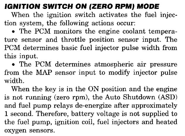
Startup takes the first sensor readings with the same routines the running software uses. Temperature readings are converted through the thermistor curve at ROM 0410. The coolant reading passes through the coolant range check (019C06). A rejected reading is not used at once: startup starts a fresh conversion and checks the new result (Fig. 8). When the second reading is also rejected, startup checks the intake air reading (019CDC) and takes the coolant substitute value (01F99A). The accepted or substituted coolant value is stored as both the working value F80A6 and the start value F80A7. The MAP reading is converted with its fallback routine (029A56), and the coolant-dependent transient fuel parameters are set (013954). The service manual describes the PCM's key-on, zero-rpm inputs in Ignition Switch On (Zero RPM) mode (Fig. 9).

FIRST COOLANT READING · 020000range check and retry
020D92JSR   0x010070; range check020D96BRCLR 0x11f,Z,#0x10,0x020dce; accepted020D9CLDE   #0x30; start conversion020DA0STE   0x770c,Z020DA4LDAA  0x770e,Z; wait for completion020DA8BPL   0x020da4020DAALDD   0x7712,Z; new reading020DAESTD   0x34,Z020DB2JSR   0x010070; check again020DB6BRCLR 0x11f,Z,#0x10,0x020dce020DBCJSR   0x010074; intake air check020DC0JSR   0x01f99a; coolant substitute020DC4LDAB  0xa6,Z020DC8STAB  0xa7,Z020DCCBRA   0x020de2020DCELDX   #0x410020DD2LDE   0x34,Z020DD6JSR   0x010050; thermistor curve020DDASTAB  0xa6,Z; working value020DDESTAB  0xa7,Z; start value
Fig. 8 Coolant Range Check with One Fresh Conversion
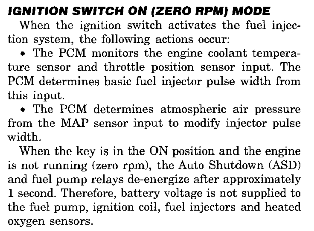
Ignition switch on, zero rpm mode: the PCM monitors coolant temperature and throttle position, determines atmospheric pressure from the MAP sensor, and de-energizes the ASD and fuel pump relays after approximately one second with the engine not running
Fig. 9 Ignition Switch On (Zero RPM) Mode (Group 14)

HANDOFF TO INTERRUPT OPERATION

The last block of startup services the watchdog with 55, AA, writes the general-purpose timer control word and clears the interrupt priority mask (Fig. 10). The routine then jumps through the bank-1 entry at 01001C to the idle branch at 028500. That instruction branches to itself.

The idle branch carries no control work. Engine events, the periodic timer and the serial interfaces enter through interrupts, and the job scheduler runs the periodic work groups from the interrupt frame (1-3 Job Scheduling). The idle branch does not service the watchdog; the first scheduled job wrapper (01FC58) does (1-5 Scheduled Jobs).

STARTUP TAIL · 020000handoff
021768LDAA  #0x5502176ASTAA  0x7a27,Z; watchdog 5502176ELDAA  #0xaa021770STAA  0x7a27,Z; watchdog AA021778LDE   #0x10202177CSTE   0x7920,Z; timer control021780ANDP  #0xff0f; open interrupt mask02179CJMP   0x01001c; to idle 028500
Fig. 10 Final Watchdog Service, Interrupt Mask and Jump to Idle

DIAGNOSIS AND TESTING

PROCESSOR EXCEPTION STOPS

Processor exceptions and unexpected interrupt levels do not return to normal operation. Each exception vector leads to a short entry that stores an exception code at F8A06, just above the retained area, and enters the port latch loop (021954). The loop repeatedly writes port C with bits 08 and 80 cleared and does not service the watchdog. The entries and their codes are listed in 1-4 Interrupts. These codes are internal processor records; they are separate from the diagnostic trouble codes described in 8-2 Fault Reporting.

REPEATED STARTUP

A wrong second reply in the companion processor check returns the main processor to the reset entry before any configuration commands are sent. Each repeat clears working memory and repeats the retained-sum check, profile selection and companion check in full.

SPECIFICATIONS

DESCRIPTIONSPECIFICATIONROM
Engine profile selector022707
Companion check byte (first profile byte)0906CA
Configuration pair5D4E2134
Engine-event watchdog preload5B2104
Startup delay loop16000 counts2108
Work group 1 period22 ticks08DC
Work group 2 period172 ticks08ED
Work group 3 period1953 ticks090A
FIRING POSITIONPROFILE ENTRYCYLINDER
101
2910
389
434
523
656
745
878
967
1012

Profile entries are zero-based cylinder numbers stored from ROM 06E4. Work group periods are scheduler ticks.

CIRCUITPCM CAVITYFUNCTION
F12C3-2Fused ignition RUN/START supply
A14C3-22Fused battery supply
Z12C3-31Ground
Z12C3-32Ground
SR1 · SYSTEM OVERVIEW1 - 3

JOB SCHEDULING

DESCRIPTION AND OPERATION

INTERRUPT-DRIVEN WORK

The PCM software has no foreground loop that calls fuel, spark and diagnostic routines in turn. Startup (020000) ends at an idle branch (028500) that jumps to itself. All recurring work enters from interrupts (1-4 Interrupts).

Two kinds of work are kept. Pending engine work is a set of eight request bits at F80D2 that engine events set; each bit selects one entry of the pending-work table. Periodic work is three groups of jobs, each released by its own countdown of scheduler ticks. Pending engine work always runs ahead of periodic work, and a periodic job can be interrupted to serve it.

The periodic interrupt (028502) supplies the tick. After it samples the converters and services timer capture, its tail decides how the tick is used (Fig. 1):

  • When engine work is in progress (F80D1, bit 04), the tick is added to the elapsed-tick count F8006 and the interrupt returns at once.
  • When a periodic job is running (F80CE, bit 02), the tick is added to F8006 (02896A). The scheduler applies it after the current job.
  • Otherwise the tick is applied directly: each group countdown decreases by one (028906).

Both of the last two paths then set the engine-work flag. When a captured engine event is waiting (F80CE, bit 04), the engine-speed routine (026CFC) runs with the interrupt mask raised and sets the pending bits for that event (2-1 Engine Position and Timing). The pending bits are then served, followed by the shared speed and serial service (01E14E), which clears the engine-work flag. If a periodic job was interrupted, the interrupt returns into that job. If not, the routine sets the scheduler-active flag, lowers the interrupt mask and enters the scheduler.

YESNOYESNOYESNOPERIODIC INTERRUPTsample · capture · timersENGINE WORK BUSY?F80D1 · bit 04COUNT TICKF8006 + 1 · returnJOB RUNNING?F80CE · bit 02COUNT TICKF8006 + 1COUNT DOWNthree groupsENGINE EVENT AND PENDING026CFC · pending bits F80D2SPEED AND SERIAL SERVICEclears engine-work flagJOB RUNNING?F80CE · bit 02RETURN TO JOBresume interrupted jobENTER SCHEDULERset F80CE · bit 02
Fig. 1 Periodic Interrupt Tail

PENDING ENGINE WORK

The engine-speed routine reads a flag byte for each engine event from the engine profile (Fig. 2). One flag requests the engine-interval history job (bit 04). Another requests spark timing: bit 10 selects spark initialization while the spark-initialization phase flag F80D1 bit 20 is set, and bit 02 selects ordinary spark timing otherwise. A third requests fuel: bit 08 selects startup fuel while the startup-fuel phase flag F80D1 bit 80 is set, and bit 01 selects running fuel otherwise. The fuel and spark jobs are described in 3-1 Fuel Amount and 4-1 Spark Timing.

The pending-work dispatcher (028992) serves the bits in order from bit 01 upward (Fig. 3). It clears the selected bit before it calls the job. The job address comes from the pending-work table at ROM 0478 (Fig. 4). After each job, when the QSPI command queue holds work (F80CD not zero), the queue service (0293F6) runs before the next bit is chosen. The dispatcher repeats until F80D2 is zero. Bits 20, 40 and 80 point to entries that return at once.

ENGINE SPEED · 026CFCpending requests
026E7CLDAB  0xbd,Z026E80CLRA  026E82TDE   026E84LDAB  E,IX; event flag byte026E86BITB  #0x10026E88BEQ   0x026e8e026E8ABSET  0xd2,Z,#0x4; interval history026E8EBITB  #0x1026E90BEQ   0x026ea2026E92BRCLR 0xd1,Z,#0x20,0x026e9e; F80D1.20?026E98BSET  0xd2,Z,#0x10; spark initialization026E9CBRA   0x026ea2026E9EBSET  0xd2,Z,#0x2; ordinary spark026EA2BITB  #0x2026EA4BEQ   0x026eb6026EA6BRCLR 0xd1,Z,#0x80,0x026eb2; F80D1.80?026EACBSET  0xd2,Z,#0x8; startup fuel026EB0BRA   0x026eb6026EB2BSET  0xd2,Z,#0x1; running fuel
Fig. 2 Engine Event Flags Set Pending Work
PENDING-WORK DISPATCH · 028992complete routine
028964ASLB  ; next bit028966ADDE  #0x2028968BRA   0x0289a4028992PSHM  IX,K028994CLRB  028996TBXK  028998LDX   #0x478; table ROM 047802899CLDAA  0xd2,Z; pending bits F80D20289A0LDAB  #0x10289A2CLRE  0289A4RORA  ; lowest bit first0289A6BCC   0x0289640289A8COMB  0289AAANDB  0xd2,Z; clear bit0289AESTAB  0xd2,Z0289B2PSHM  D,E,IX,IY,IZ,K0289B4AEX   0289B6LDX   0x0,X0289B8JSR   0x1:0x0,X; call job0289BCPULM  K,IZ,IY,IX,E,D0289BETST   0xcd,Z; QSPI queue waiting?0289C2BEQ   0x0289cc0289C4PSHM  D,E,IX,IY,IZ,K0289C6JSR   0x01002c; serve queue0289CAPULM  K,IZ,IY,IX,E,D0289CCTST   0xd2,Z; more pending?0289D0BNE   0x0289980289D2PULM  K,IX0289D4JMP   0x010020; speed and serial service
Fig. 3 Pending-Work Dispatcher
PENDING-WORK DISPATCHrecords
BITSTORED TARGETHANDLERROUTINE NAME
010109DC0109DCcompute and queue fuel pulsewidth
0201015A01015Acompute and queue spark advance
04016A36016A36process engine interval history and dispatch
08011B14011B14compute startup fuel pulsewidth
100100E80100E8initialize spark command and post start mode
200100B40100B4Routine 0100B4
400100B60100B6Routine 0100B6
800100B80100B8Routine 0100B8

ROM 000478–000487 · 16 bytes · Read by 028992

Fig. 4 Pending-Work Dispatch Table — complete entry 9-6, Fig. 2

PERIODIC WORK GROUPS

The number of periodic groups is stored at ROM 040E (3). ROM 0464 holds a pointer to each group descriptor. A descriptor begins with the group's reload count in ticks, followed by three-byte job records: a two-byte job address and a state byte. A word of FFFF ends the group (Fig. 8). The complete group listings are in 10-2 Work Schedule Tables.

Each group keeps three values in RAM: a countdown (F8000, F8002, F8004), a record cursor (F8014, F8016, F8018) and a state byte (F8028, F8029, F802A). Startup loads each countdown from its descriptor (1-2 Startup and Initialization).

When a countdown reaches zero, it is reloaded with the group period (Fig. 5). An idle group (state zero) becomes ready: its cursor is set to the first record and its state to that record's state byte. A group that is still working through its records is not restarted; its state receives bit 80 instead, which marks the pass as overrun. A release that occurs during an overrun pass adds no further mark.

GROUP COUNTDOWN · 028906one tick
028928DECW  0x0,Z; countdown − 102892CBNE   0x02895202892EPSHM  IX,IY028930AEY   028932LDY   0x0,Y028934LDD   0x0,Y; reload count028936STD   0x0,Z028938LDAB  0x0,X; group state02893ABEQ   0x02894202893CORAB  #0x80; overrun mark02893ESTAB  0x0,X028940BRA   0x028950028942AIY   #0x2; first record028944LDAA  0x2,Y; first state byte028946STAA  0x0,X028948LDX   #0x801402894CAEX   02894ESTY   0x0,X; record cursor028950PULM  IY,IX028952AIZ   #-0x2028956AIX   #-0x102895ASUBE  #0x2; next group02895EBPL   0x028928
Fig. 5 Group Countdown and Release

JOB SELECTION AND EXECUTION

The scheduler selects the group whose state byte has the greatest low-order digit (028B6A, Fig. 6). The state byte of a group's current record is therefore its priority. All records carry state 08 except the fourth record of group 1, which carries 07. Within a pass the scan begins at the group selected last, and a later group of equal value replaces the earlier choice, so groups of equal priority take turns. When no group is ready, the scheduler clears the scheduler-active flag and returns from the interrupt to the idle branch or to the interrupted code.

The record service (028BB4) calls one job, then advances the cursor by one record (Fig. 7). The group state is updated as follows:

  • Next record present, no overrun mark: the state becomes that record's state byte.
  • Next record present, overrun mark set: when the next state byte is lower than the first record's, the group restarts at its first record; otherwise the group continues and keeps the mark.
  • End of group, no overrun mark: the state is cleared and the group is idle.
  • End of group, overrun mark set: the group restarts at its first record.

In group 1, an overrun pass therefore returns to the first record without running the fourth job.

After each job the scheduler checks F8006. When ticks have accumulated, the update service (028C4A) subtracts them from all three countdowns. A countdown that reaches or passes zero is released as described above; when the overshoot is smaller than the period, the remainder is carried into the new count. The consumed ticks are then subtracted from F8006 with the interrupt mask raised, so ticks that arrive during this update are kept. The scheduler then selects again.

SELECT READY GROUP · 028B6Acomplete routine
028B6ACLRD  028B6CPSHM  D028B6ETSY   028B70LDAB  #0xf028B72TBXK  028B74LDX   #0x8028; group states F8028028B78LDE   0x0,Y; start at last group028B7CCLRD  028B7EPSHB  028B80LDAB  E,IX028B82ANDB  #0xf; priority digit028B84STAB  0x139,Z028B88PULB  028B8ACMPA  0x139,Z; best so far028B8ELBLE  0x028cde; equal or greater wins028B92ADDE  #0x1028B94CPE   0x40e; group count ROM 040E028B98BCS   0x028b9c028B9ACLRE  028B9CCPE   0x0,Y028BA0BNE   0x028b7e028BA2CMPA  #0x0; none ready028BA4LBEQ  0x028ce8028BA8CLRA  028BAATDE   028BACSTE   0x0,Y; remember group028BB0JMP   0x010064; run one record
Fig. 6 Ready-Group Selection
NOYESYESNOSELECT READY GROUPhighest priority · turnsGROUP READY?state not zeroEND PASSclear F80CE.02 · RTIRUN ONE RECORDcall job · advance cursorUPDATE GROUP STATEnext · restart · idleTICKS WAITING?F8006 not zeroAPPLY TICKSrelease due groupsSELECT AGAINreturn to top
Fig. 7 Scheduler Pass
PERIODIC WORK GROUP 1records
RECORDSTATE BYTESTORED TARGETHANDLERROUTINE NAME
0008DE0801FC5801FC58service fast vehicle state and shared port group
0008E10801FC8E01FC8Eservice periodic engine control group
0008E40801FCBC01FCBCservice fast watchdogs and diagnostics
0008E70701FCF601FCF6service fast purge oxygen and companion group

ROM 0008DC–0008E9 · 14 bytes · Read by 028502

Fig. 8 Periodic Work Group 1 — complete entry 9-6, Fig. 8

INTERRUPTED JOBS

A periodic job runs with the interrupt mask lowered. When the next periodic interrupt arrives during the job, its tail finds the scheduler-active flag set: the tick is counted, captured engine events and pending engine work are served, and the interrupt returns into the job. A second scheduler pass never starts on top of the first. Engine work thus interrupts periodic work, while periodic work never interrupts engine work. The jobs in each group are described in 1-5 Scheduled Jobs and 1-6 Supporting Jobs.

SPECIFICATIONS

DESCRIPTIONSPECIFICATIONROM
Number of periodic groups3040E
Group 1 descriptor08DC0464
Group 2 descriptor08ED0466
Group 3 descriptor090A0468
Group 1 period (four jobs)22 ticks08DC
Group 2 period (eight jobs)172 ticks08ED
Group 3 period (twelve jobs)1953 ticks090A
Pending-work table, first entry09DC (job 109DC)0478

Periods are counted in periodic-interrupt ticks. Job addresses in the tables are offsets in bank 1.

RAMCONTENTS
F8000–F8005Group countdowns, one word per group
F8006Elapsed ticks waiting to be applied
F8008Tick count being applied
F8014–F8019Group record cursors
F8028–F802AGroup state bytes (priority digit, bit 80 overrun mark)
F80CDQSPI queue work waiting (not zero)
F80CEBit 02 scheduler active; bit 04 engine event captured
F80D1Bit 04 engine work in progress
F80D2Pending engine-work bits 01–80

CALIBRATION STRUCTURES

STRUCTUREROMTYPEREFER TO
Pending-work dispatch000478records9-6, Fig. 2
Periodic work group 10008DCrecords9-6, Fig. 8
Periodic work group 20008EDrecords9-6, Fig. 9
Periodic work group 300090Arecords9-6, Fig. 10
1 - 41 · SYSTEM OVERVIEWSR

INTERRUPTS

DESCRIPTION AND OPERATION

INTERRUPT-DRIVEN OPERATION

The PCM software runs from interrupts. When the startup routine (020000) finishes, it jumps to an instruction at 028500 that branches to itself (028500). The program performs no work at that location. Sensor collection, engine-event processing, fuel and spark computation, the scheduled jobs and the diagnostic data stream are all entered from interrupt handlers. Startup enables interrupts before its own work is complete, so startup and interrupt service overlap. Refer to 1-2 Startup and Initialization.

The vector table begins at ROM 000000. Each vector number has a 16-bit slot at twice its number, so vector 38 occupies slot 0070. The 252 slots from 000008 to 0001FE lead to two kinds of destination (Fig. 2):

  • Four returning routes. The periodic interrupt, the engine-event capture, the level-5 request and the SCI transmit interrupt. Each handler saves the CPU registers, sets the common RAM base to F8000, performs its work and returns to the interrupted code with an RTI instruction.
  • Fault traps. The remaining 248 slots lead to 14 trap entries that never return.
VECTORSLOTENTRYHANDLERSELECTED BY
3800700402Periodic interrupt service 028502Periodic interrupt control value 0338
4100820406Engine-event capture 028F24Timer interrupt configuration 0440, capture channel 1
15002A040ALevel-5 request 029F90Level-5 autovector
4E009C—SCI transmit 00EC5ASCI setup 00EC08

The first three slots point to jump instructions in the bank-0 entry area; the SCI slot points directly at its handler. Five RTI instructions serve the four routes: 028CF2 (periodic service and job scheduler), 02926E (capture), 029FA8 (level 5), and 00ECA8 and 00ECC0 (SCI).

Fig. 1 Interrupt Routes
INTERRUPT-VECTOR ADDRESSESrecords
VECTOR OFFSETENTRY TARGETFINAL ROUTEKIND
0000080008220218C0fault trap
00000A0008260218CAfault trap
00000C00082A0218DCfault trap
00000E00082E0218E6fault trap
0000100008320218F0fault trap
00001200081E02194Afault trap
00001400081E02194Afault trap
00001600081E02194Afault trap
00001800081E02194Afault trap
00001A00081E02194Afault trap
00001C00081E02194Afault trap
00001E0008360218FAfault trap

240 more records in 9-6, Fig. 1

ROM 000008–0001FF · 504 bytes

Fig. 2 Interrupt Vector Table — complete entry 9-6, Fig. 1

PERIODIC INTERRUPT

The periodic interrupt service (028502) is the time base of the program. Startup writes the control value 0338 to the periodic interrupt control register, which selects vector 38. Each pass performs the following work:

  • Analog collection. The service waits for the analog converter to report a completed sequence and stores the results. Port C bits 10 and 40 are inverted on every pass, and the new state selects the result block: F8032–F8041, with five results scaled by the factor at F831D and limited to FFC0, or F8042–F804D unscaled. Before it leaves, the service writes the converter control word that starts the next sequence.
  • Timer service. The free-running timer count is copied to F8050, timer overflows are counted at F8052, and vehicle speed sensor pulses are timestamped. Refer to 6-1 Vehicle Speed Input.
  • Scheduler tick. The tail of the service decides how the tick is counted (Fig. 3).

The tail counts the tick in one of three ways: into the elapsed-tick count F8006 when event maintenance is already in progress (F80D1, bit 04), through 02896A when a scheduled job was interrupted (F80CE, bit 02), or directly into the group countdowns through 028906. The service then sets F80D1 bit 04 and performs event maintenance: the engine speed routine (026CFC) when the capture handler has recorded an engine event (F80CE, bit 04), the pending-work dispatcher (028992) and the shared tail (01E14E), which services the command queue, vehicle speed and SCI status. It then returns to an interrupted job, or enters the job scheduler (028B6A), which leaves through the RTI at 028CF2. The complete tick path is shown in 1-3, Fig. 1; the scheduler is described in 1-3 Job Scheduling.

PERIODIC INTERRUPT SERVICE · 028502tick tail
0288BALDE   #0x30; converter control0288BESTE   0x770c,Z; start next sequence0288E8BRCLR 0xd1,Z,#0x4,0x0288f6; busy0288EEINCW  0x6,Z; elapsed ticks F80060288F2JMP   0x010014; restore and RTI0288F6BRCLR 0xce,Z,#0x2,0x028900; job active0288FCJMP   0x010018; accumulate tick028900PSHM  IZ,K028902JMP   0x010054; count down groups
Fig. 3 Periodic Service Tail

ENGINE-EVENT CAPTURE

Startup writes the timer interrupt configuration 0440, which places the timer vectors at 40; input-capture channel 1 uses vector 41. The capture handler (028F24) records each engine event and leaves the computation to the periodic service (Fig. 4):

  • The event time is read from the timestamp words at 50004 and 50006 and stored at F813B, and the capture flag is cleared.
  • If the previous event flag is still set, the counter at F80BE increments. The handler then sets F80CE bits 04 and 40 and F80CF bit 08, and increments the event count at F8054.
  • The two engine-event watchdog counters F80C6 and F80C7 reload from ROM. The fast watchdog job (013E3E) counts them down; an expired counter starts the event-loss path. Refer to 2-2 Loss of Engine Events.

On the first captured event (F80CE, bit 10 clear), the handler clears the event-loss requests (F8106 bits 40 and 80, F8108 bit 04) and, unless F80CC bit 40 is set, queues output command 04 and, when the queue has room, command 2D. The complete first-event sequence is described in 2-2 Loss of Engine Events; the commands in 5-1 Output Commands.

At engine speeds at or above 5500 rpm, with F80BC bit 40 set, the handler also queues the prepared fuel word for the bank selected by F80BC bit 20 (F82B0 or F82B2) as command 13 and services the command queue before it returns. Below that speed the fuel job (0109DC) sends the word itself. Refer to 3-1 Fuel Amount.

ENGINE-EVENT CAPTURE · 028F24entry
028F38LDE   0x6; timestamp 50006028F3CLDD   0x4; timestamp 50004028F40ANDA  #0xf028F42BCLR  0x7922,Z,#0x1; clear capture flag028F46STE   0x13b,Z028F4ASTD   0x13d,Z028F4ECLRB  028F50TBEK  028F52LDAA  0x7a19,Z028F56STAA  0xc5,Z028F5ABRCLR 0xce,Z,#0x4,0x028f64; prior event028F60INC   0xbe,Z; unconsumed events028F64BSET  0xce,Z,#0x44; event captured028F68BSET  0xcf,Z,#0x8028F6CINCW  0x54,Z; event count028F70LDAA  0x2100; ROM 2100028F74STAA  0xc6,Z028F78LDAA  0x2101; ROM 2101028F7CSTAA  0xc7,Z
Fig. 4 Engine-Event Capture Entry

LEVEL-5 REQUEST

The command-queue service (0293F6) sets bit 20 of register FFA1F when it finishes with transfers still pending (F80CD or F80E4 nonzero); startup clears the register. The level-5 handler (029F90) clears bit 20, calls the queue service through 01002C, restores the registers and returns (Fig. 5). Pending output commands therefore receive service outside the periodic and capture handlers.

LEVEL-5 HANDLER · 029F90complete routine
029F90PSHM  D,E,IX,IY,IZ,K; save registers029F92LDAB  #0xf029F94TBZK  029F96LDZ   #0x8000; RAM base F8000029F9ACLRB  029F9CTBEK  029F9EBCLR  0x7a1f,Z,#0x20; clear FFA1F bit 20029FA2JSR   0x01002c; command-queue service029FA6PULM  K,IZ,IY,IX,E,D029FA8RTI   ; return
Fig. 5 Level-5 Handler
COMMAND-QUEUE SERVICE · 0293F6exit
0296C8TST   0xcd,Z; transfers pending0296CCBNE   0x0296d60296CETST   0xe4,Z; queue entries0296D2BNE   0x0296d60296D4BRA   0x0296e60296D6BCLR  0xcc,Z,#0x800296DALDAA  0x7a1f,Z0296DEORAA  #0x20; set FFA1F bit 200296E0STAA  0x7a1f,Z0296E4BRA   0x0296ea0296E6BCLR  0xcc,Z,#0x800296EARTS   
Fig. 6 Command-Queue Service Exit

SCI TRANSMIT INTERRUPT

The DRB scan tool communicates with the PCM over the SCI circuits (Fig. 7). The SCI setup routine (00EC08) selects one of five address lists through the pointer table at ROM F659, clears the list position at F8345, writes interrupt vector 4E and enables the transmit interrupt.

Each transmit interrupt (00EC5A) reads the next list entry and sends one byte from working RAM. Addresses from F8000 up to, but not including, F8A05 are permitted. The stream ends when the next entry is FFFF or after 32 positions; an address outside the permitted range sends zero and ends the stream. At the end the handler disables the transmit interrupt. The stream reads only the listed RAM bytes. Refer to 8-1 Diagnostic Overview.

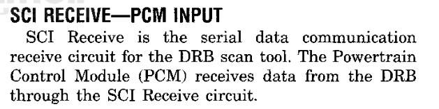
SCI Receive is the serial data communication receive circuit for the DRB scan tool
Fig. 7 SCI Receive (Group 14)

FAULT TRAPS

Each of the 248 fault slots leads to a short trap entry that stores a marker byte at F8A06 and jumps to the trap loop (021954). The marker is the vector number; the 235 unused slots share the default entry (02194A), which stores FF. The bus-error entry (0218CA) reloads the RAM base before it stores its marker. The trap loop clears port C bits 80 and 08 and repeats the port write indefinitely (Fig. 8). A trap does not return to the interrupted work.

The marker is a CPU exception number. It is not a diagnostic trouble code and is not a blink code. Refer to 8-2 Fault Reporting.

VECTOREXCEPTIONENTRYMARKER
04Breakpoint0218C004
05Bus error0218CA05
06Software interrupt0218DC06
07Illegal instruction0218E607
08Divide by zero0218F008
0FUninitialized interrupt0218FA0F
11–14Level 1–4 autovectors021904–02192211–14
16–17Level 6–7 autovectors02192C, 02193616–17
18Spurious interrupt02194018
all othersUnused02194AFF
TRAP LOOP · 021954complete routine
021954LDAA  0x7a41,Z; port C021958ANDA  #0x77; clear bits 80, 0802195ASTAA  0x7a41,Z; write port02195EBRA   0x02195a; repeat
Fig. 8 Fault Trap Loop

SPECIFICATIONS

DESCRIPTIONSPECIFICATIONROM
Vector 38 slot, periodic interrupt04020070
Vector 41 slot, engine-event capture04060082
Vector 15 slot, level-5 request040A002A
Vector 4E slot, SCI transmitEC5A009C
Periodic interrupt control value03380201A0
Periodic timer value0004020198
Timer interrupt configuration04400201D2
Engine-event watchdog reload, F80C673 counts2100
Engine-event watchdog reload, F80C780 counts2101
Capture handler sends fuel word at or above5500 rpm2138
SCI stream, maximum list position1F (32 positions)00EC95
SCI stream, lowest permitted addressF800000EC7E
SCI stream, first excluded addressF8A0500EC84

Values at 0201xx and 00ECxx are instruction operands in the startup and SCI routines. Engine speed converts at one rpm per eight counts.

CIRCUITPCM CAVITYFUNCTION
D21C1-27SCI transmit (PCM perspective)
D20C1-29SCI receive (PCM perspective)

CALIBRATION STRUCTURES

STRUCTUREROMTYPEREFER TO
Interrupt-vector addresses000008records9-6, Fig. 1
SR1 · SYSTEM OVERVIEW1 - 5

SCHEDULED JOBS

DESCRIPTION AND OPERATION

JOB GROUPS

The scheduler releases three periodic groups of jobs, reloaded every 22, 172 and 1953 scheduler ticks (1-3 Job Scheduling). This section describes the smaller jobs that collect readings, keep counters and prepare output requests. The larger control functions have their own sections.

A job runs on every visit of its group, but most jobs test a counter, a flag or the command queue first and return without change when the test fails. The fast group calls its jobs through four wrapper routines. The medium and slow groups call each job from its own schedule record (Fig. 1).

JOBROUTINEGROUPCALLED FROM
Shared port drive and release01A02A · 01A04AFast01FC58
Shared port mismatch and fault checks01A058 · 01A138Fast01FC8E
Temperature filters01391EFast01FC8E
Road-speed sample expiry01E114Fast01FCBC
Power input and retained state013A66Fast01FCBC
External status bitfields018A7CMediumRecord 0008F2
Fuel timers and injector offset013426MediumRecord 0008F5
External status and configuration014136MediumRecord 0008F8
Running-age counter0139F4SlowRecord 00090C
Injector offset command01365CSlowRecord 00090F
Running-age correction013720SlowRecord 00092A
Radiator fan requests01FA22SlowRecord 00092D
PERIODIC WORK GROUP 3records
RECORDSTATE BYTESTORED TARGETHANDLERROUTINE NAME
00090C080139F40139F4tick engine running age counter
00090F0801365C01365Cqueue injector offset curve command
0009120801009002246Eseed empty idle air position state
00091508013D90013D90service engine event loss output state
00091808013490013490tick coolant gated fuel counter
00091B080100A40251FCservice fuel level sensor and filter
00091E0801F2E201F2E2service diagnostic timeouts and output restore
00092108010098023B0Cservice transmission temperature
0009240801363E01363Etick temporary fuel cut profile
0009270801F87401F874merge selected cylinder fuel inhibit masks
00092A08013720013720update running age coolant correction
00092D0801FA2201FA22control cooling fan requests

ROM 00090A–00092F · 38 bytes · Read by 028502

Fig. 1 Slow Periodic Group — complete entry 9-6, Fig. 10

RADIATOR FAN CONTROL

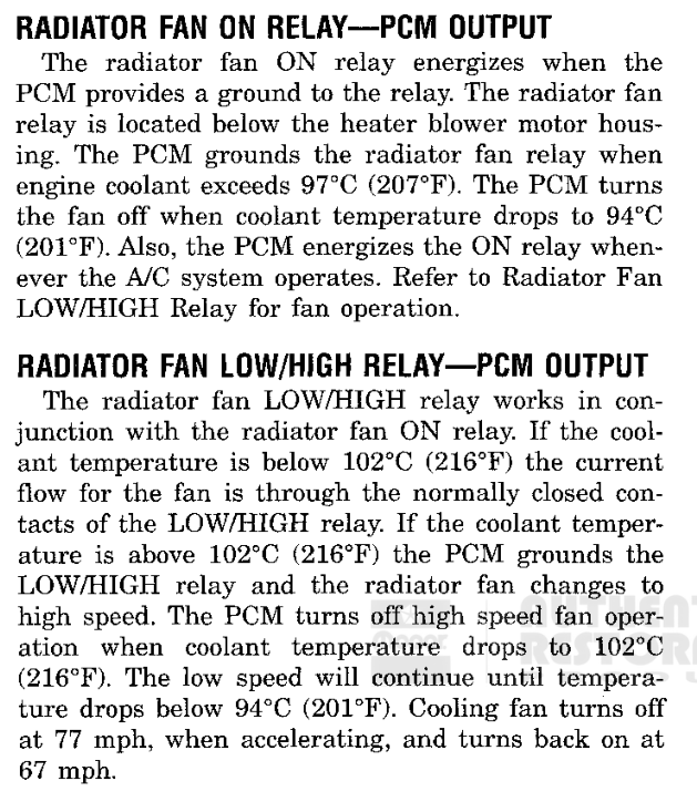
The PCM controls the radiator fan through two relays: the radiator fan ON relay and the radiator fan LOW/HIGH relay (Fig. 5). The fan job (01FA22) runs last in the slow group. It holds the ON relay request in F8107, bit 40, and the LOW/HIGH relay request in F8108, bit 01. The job compares the coolant value against calibrated pairs of thresholds, and the pair in use depends on road speed and on the present state of each request (Fig. 2).

The job returns without change when calibration option 2709 bit 80 is set, or when F8128 bit 08 is set. While the engine-running flag F80D1.40 is clear, the job sets F8107.40, so the fan does not run during cranking. When the coolant sensor fault flag F8808.80 is set, the job clears F8107.40 and moves to high speed, the limp-mode operation the manual describes (Fig. 4).

In normal operation, and with option 2709 bit 40 set, the high-speed stage is tested first. Below the road-speed threshold, the LOW/HIGH request is applied at 102 °C and released below 98 °C. Release sets F8108.01 and clears F8107.40, so the fan returns to low speed. The change to high speed is delayed: each pass decrements a countdown at F868C, loaded with 4, and F8108.01 clears only when the countdown reaches zero.

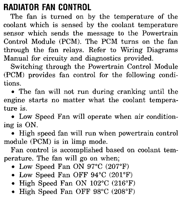
While the LOW/HIGH request is released and coolant is below the high-speed threshold, the low-speed stage runs. Below the road-speed threshold the job clears F8107.40 at 97 °C and sets it again below 94 °C (Fig. 3). These are the fan ON and OFF temperatures documented in the service manual. When F810B bits 02 and 04 are both set, the job requests low speed without testing coolant.

Each stage keeps its own road-speed flag (F8674.04 for the low-speed stage, F8674.02 for the high-speed stage). The flag sets below raw speed B4 and clears only at C8, so the band does not cycle. Above the threshold the job uses a second pair of temperatures, 184 °C and 190 °C, which releases the fan at road speed. The manual documents this as the fan turning off at 77 mph and back on at 67 mph.

The ON and LOW/HIGH relay requests leave the PCM through the output-command service (5-1 Output Commands). The PCM grounds the ON relay on circuit C27 and the LOW/HIGH relay on circuit C137.

yesnono faultFAN JOBslow group · record 00092DENGINE RUNNINGF80D1.40COOLANT SENSOR FAULTF8808.80 · fan on high speedHIGH-SPEED STAGE271B / 271C · speed band F8674.02LOW-SPEED STAGE2715 / 2716 · speed band F8674.04FAN REQUESTSF8107.40 on · F8108.01 low/highFAN OFFset F8107.40COUNTDOWNF868C · reload 3D70DRB FAN TESTS00E470 · 00E93C · 00E986
Fig. 2 Radiator Fan Request Path
RADIATOR FAN REQUESTS · 01FA22low-speed stage
01FAAABRCLR 0x674,Z,#0x4,0x01fab6; speed band flag01FAB0LDAA  0x271401FAB6LDAA  0x271301FABALDAB  0xa6,Z01FABECMPA  0xa4,Z; road speed01FAC4BSET  0x674,Z,#0x401FAC8BRSET 0x107,Z,#0x40,0x01fad6; fan on?01FACECMPB  0x2715; off below01FAD2BCS   0x01fb3e01FAD6CMPB  0x2716; on at or above01FADABCC   0x01fb22
Fig. 3 Low-Speed Stage Thresholds
Radiator fan control: no fan during cranking, low speed with A/C, high speed in limp mode, and the low and high speed on and off temperatures
Fig. 4 Radiator Fan Control (Group 7)
Radiator fan ON relay and LOW/HIGH relay operation, with coolant temperatures and the 77 mph and 67 mph road-speed cut-out
Fig. 5 Radiator Fan Relays (Group 14)

COUNTERS AND CORRECTIONS

Temperature filters. The temperature filter job (01391E) does its work only when the low six bits of counter F8097 equal 3E. On that visit it decrements the countdowns at F8024 and F83E3, runs the coolant temperature filter (01F926) and the intake air temperature filter (01F8BC), and calls the RPM-drop fuel preparation (1-6 Supporting Jobs). While the engine is stopped it also gives the blink-code formatter (013EF4) its turn (8-3 Blink Code Display).

Running age. The running-age job (0139F4) increments the counter at F80C4 on each slow-group visit while the engine-running flag is set. The counter stops at FF. The engine-speed routine clears it when the engine returns to the startup-fuel phase (2-1 Engine Position and Timing).

The running-age correction (013720) reads that counter together with the coolant temperature recorded at start (F80A7). After a delay of 0 counts it takes a value from the curve at 32F1 and tapers it to zero over 0 further counts. The result is stored at F82D2. Both calibration values are zero in this image, so the routine stores zero on every visit (Fig. 6).

RUNNING-AGE CORRECTION · 013720complete routine
013720CLRB  013722LDAA  0x32f0; taper length013726ADDA  0x32ef; delay01372ACMPA  0xc4,Z; running age01372EBCS   0x01376a013730LDAA  0x32ef013734CMPA  0xc4,Z013738BHI   0x01376e01373ACLRB  01373CTST   0x32f0013740BEQ   0x01376a013742LDX   #0x32f1013746LDAA  0xa7,Z; coolant at start01374AJSR   0x010030; curve 32F101374ELDAB  0x32ef013752ADDB  0x32f0013756SUBB  0xc4,Z01375AMUL   ; scale by remaining counts01375CXGDX  01375ECLRA  013760LDAB  0x32f0013764XGDX  013766IDIV  ; divide by taper013768XGDX  01376ASTAB  0x2d2,Z; correction F82D201376ERTS   
Fig. 6 Running-Age Correction

Injector offset. The medium-group fuel timer job (013426) reads the injector offset curve with the value at F816E and stores the curve result at F826F. The slow-group job 01365C sends that byte to the companion processor as command 1D, select 1D, when fewer than nine commands wait in the queue (F80E4). The command carries the curve result only. The medium-group job (013426) also forms the complete signed injector offset at F82B4 (3-1 Fuel Amount).

INJECTOR OFFSET VS INPUTcurve
105 → 182113 → 151130 → 107146 → 79162 → 57194 → 35227 → 16255 → 0Input 105–255Output 0–182 raw counts
Points (8)
INPUTOUTPUT (RAW COUNTS)
105182
113151
130107
14679
16257
19435
22716
2550

ROM 002DEE–002DFE · 17 bytes · Read by 013426

Fig. 7 Injector Offset Curve — complete entry 9-2, Fig. 3

STATUS REQUESTS

Two medium-group jobs queue requests to the companion processor through the command queue (029270). Each request is queued only when the queue has room. The status and configuration job (014136) sends command 2A, select 1E, which returns the value at F816E used by the injector offset curve. It also sends command 25, which returns F82D9, and a set of configuration requests. The bitfield job (018A7C) sends commands 7A, select 1D, and 69, select 1E, and decodes the returned bits through the tables at C26E and C274.

SHARED PORT AND SPEED SAMPLE SERVICES

Four request bits share pins on processor port GP. Inside the first fast wrapper (01FC58), the drive routine copies bits 3 to 6 of the request byte F8502 to PORTGP and makes those pins outputs. Two calls later, after the throttle reference and barometric pressure updates, the release routine returns the same pins to inputs (Fig. 8). The reverse lockout request travels on this port (6-3 Reverse Lockout).

In the second fast wrapper, the mismatch routine (01A058) compares PORTGP bits 5 and 6 with the request byte. A bit requested set that reads clear is latched in F84FE; a bit requested clear that reads set is latched in F84FF. The fault qualification routine (01A138) checks PORTGP bits 3 and 4 against their requests with the counters at F84EC and F84ED, and latches F8496 bits 01 and 02.

SHARED PORT DRIVE · 01A02Acomplete routine
01A02ALDAA  0x502,Z; request byte F850201A02EANDA  #0x78; bits 3–601A030LDAB  #0x7801A032COMB  01A034ANDB  0x7907,Z01A038ABA   01A03ASTAA  0x7907,Z; PORTGP01A03ELDAB  0x7906,Z01A042ORAB  #0x78; pins to outputs01A044STAB  0x7906,Z; DDRGP01A048RTS   
Fig. 8 Shared Port Drive Phase

Speed sample expiry. The periodic interrupt service (028502) reloads a lifetime count at F80A3 with each fresh sample. The expiry job (01E114) decrements a nonzero count and returns. A visit that finds the count at zero clears the road-speed value at F80A4, the working words at F8135 and F8648, and flag F80D6.01. With option 2707 bit 02 set, it also loads FFFF into the words at F8084 and F8086 (6-1 Vehicle Speed Input).

RETAINED STATE

The power input job (013A66) follows a state machine driven by PORTF0 bit 01. On its hold paths it sums the 515 bytes of retained working memory F8802 to F8A04 (013D08) and stores the 16-bit sum at F8800. One path clears F89A6 before taking the sum. At the next reset, the startup code compares the sum with F8800: a match preserves retained state, and a mismatch reinitializes it (1-2 Startup and Initialization).

RETAINED MEMORY SUM · 013D08complete routine
013D08LDAB  #0xf013D0ATBXK  013D0CCLRD  013D0ELDX   #0x8802; first byte F8802013D12ADDB  0x0,X; add byte013D14BCC   0x013d18013D16INCA  ; carry to high byte013D18AIX   #0x1013D1ACPX   #0x8a05; end F8A05013D1EBCS   0x013d12013D20RTS   
Fig. 9 Retained Working Memory Sum

DIAGNOSIS AND TESTING

DRB OUTPUT TESTS

The DRB radiator fan tests operate the same request bits as the fan job. A test therefore exercises the same output path as normal fan control.

DRB TESTROUTINEACTION
Radiator fan00E470Changes F8107.40 and F8108.01
Low-speed fan00E93CSets F8108.01, toggles F8107.40
High-speed fan00E986Clears F8108.01, toggles F8107.40
Generator field00E5A6Sends a companion command

DIAGNOSTIC TROUBLE CODES

The PCM monitors both fan relay control circuits. An open or shorted circuit sets the code shown in Fig. 10.

Trouble code table rows: code 35, P1490 low speed fan control relay circuit and P1489 high speed fan relay circuit
Fig. 10 Fan Relay Circuit Codes (Group 25)

SPECIFICATIONS

DESCRIPTIONSPECIFICATIONROM
Fan job option byte (bit 80 disables, bit 40 enables two speeds)472709
Low-speed fan on at or above (below speed threshold)97 °C2716
Low-speed fan off below (below speed threshold)94 °C2715
Low-speed fan on at or above (above speed threshold)190 °C2718
Low-speed fan off below (above speed threshold)184 °C2717
High-speed fan on at or above (below speed threshold)102 °C271C
High-speed fan off below (below speed threshold)98 °C271B
High-speed fan on at or above (above speed threshold)190 °C271E
High-speed fan off below (above speed threshold)184 °C271D
Low-speed stage speed band, enter below / leave at (raw)B4 / C82713–2714
High-speed stage speed band, enter below / leave at (raw)B4 / C82719–271A
High-speed step countdown4 passes3D70
Running-age correction delay0 counts32EF
Running-age correction taper0 counts32F0

Coolant temperature is the stored value minus 64 °C. Road speed is the raw value of F80A4.

CIRCUITPCM CAVITYFUNCTION
C27C1-2Radiator fan ON relay control
C137C1-21Radiator fan low/high relay control
1 - 61 · SYSTEM OVERVIEWSR

SUPPORTING JOBS

DESCRIPTION AND OPERATION

IDLE AIR CONTROL

The PCM adjusts idle speed through the idle air control motor (Fig. 3). The software keeps two positions for the motor: the requested position at F8612 and the tracked position at F8810. The idle air service (021960) runs in the first fast wrapper. It updates the requested position from the engine-running state, the settle count at F8614 and its target, speed, pressure and A/C transition corrections (5-3 Idle Air Control).

At the end of each pass the service hands the request to the movement routine (0223B6) when the supply value at F816E is at or above 7A and engine speed is at or below 8000 rpm. The movement routine takes the difference between the tracked and requested positions and limits each move to 1F steps. While F8847 bit 80 is set, a move waits for the previous reply and is limited to 3 steps. The routine updates the tracked position by the amount moved and forms a command byte: the step count in the low five bits, the direction and mode in the upper bits (Fig. 2).

The queue routine (022432) marks the reply byte F8615 pending (FF) and sends the byte as command 22, select 1E. Calibration option 2708 bit 40 blocks the command; the bit is clear in this image. The reply is polled into F8615 by 022452. In the reset mode (F880F bit 08) the routine counts the tracked position down to zero.

When both positions are zero and F80D6 bit 01 is clear, the slow-group seed job (02246E) loads 2 into both and sets F880F bit 04. The three DRB idle air tests write the same requested position, so a test moves the motor through the normal movement path (Fig. 1).

IDLE AIR SERVICEfast groupDRB IAC TESTS13-07 · 13-3B · 13-3CSEED JOBslow groupREQUESTED POSITIONF8612MOVEMENTtracked F8810 · at most 1F stepsCOMMAND 22, SELECT 1Ereply pending F8615IDLE AIR CONTROL MOTORK39 · K40 · K59 · K60
Fig. 1 Idle Air Position Path
IDLE AIR MOVEMENT · 0223B6step and direction
0223C4LDAB  0x810,Z; tracked position0223CESUBB  0x612,Z; minus requested0223D2BCC   0x0223d60223D4NEGB  0223D6BEQ   0x022430; no move0223D8CMPB  #0x1f; limit 1F0223DABCS   0x0223de0223DCLDAB  #0x1f02240ELDAA  0x810,Z022412CMPA  0x612,Z022418SBA   ; move down02241ASTAA  0x810,Z02241EORAB  #0xa0; direction bits022422ABA   ; move up022424STAA  0x810,Z022428ORAB  #0x2002242AORAB  #0x4002242CJSR   0x022432; queue command 22
Fig. 2 Idle Air Movement Command
Idle air control motor location on the intake manifold, pintle operation and the inputs that affect idle speed
Fig. 3 Idle Air Control Motor (Group 14)

FUEL LEVEL INPUT

The fuel level job (0251FC) runs in the slow group. Calibration option 6F8C bit 80 selects the source of the reading. With the bit clear, as in this image, the job reads two values from the companion processor. Command 02, select 1E, returns F863E, the value the DRB reports as fuel level sensor voltage. Command 03, select 1E, returns F8670, the value the job filters.

A value of 97 or above is not filtered. After FF such visits in a row the job sets F8497 bit 40; after 1E visits below that value it clears the bit. While the bit is set the job saves the estimate, marks it FFFF and blends no new readings. When the bit clears and F880A bit 08 is clear, the saved estimate is restored.

The job smooths F8670 with the fractional filter (010048) and converts it through the curve at 214E. The result is stored at F8666 and at F863F, the fuel level percent reported to the DRB. A long-term estimate at F89A0 then follows the curve result through the weighted blend (025424): the old value is multiplied by the weight, the new result is added in the high byte, and the sum is divided by the weight plus one (Fig. 5).

The weight depends on road speed. The job counts consecutive visits at zero road speed in F8665. After 60 stopped visits the estimate blends with weight 9. Below that count, the weight is 300, and a reading that differs from the estimate by 33 or more is not blended.

FUEL LEVEL JOB · 0251FCweight selection
025336LDD   0x9a0,Z; estimate F89A002533ASUBA  0x666,Z; minus curve result02533EBCC   0x025342025340NEGA  025342BRSET 0x658,Z,#0x40,0x025378025348LDAB  0x665,Z; stopped visits02534CCMPB  0x2148; stopped limit025350BCS   0x025362025352LDE   0x2149; stopped weight025356LDX   0x214902535AAIX   #0x102535CJSR   0x025424; blend025360BRA   0x02538e025362CMPA  0x2147; difference limit025366BCC   0x02538e025368LDE   0x214b; moving weight02536CLDX   0x214b025370AIX   #0x1025372JSR   0x025424025376BRA   0x02538e
Fig. 4 Fuel Level Blend Weight Selection
FUEL LEVEL BLEND · 025424complete routine
025424LDD   0x9a0,Z; estimate025428EMUL  ; times weight02542AADDA  0x666,Z; add result, high byte02542EADCE  #0x0025432EDIV  ; divide by weight + 1025434XGDX  025436STD   0x9a0,Z; new estimate02543ARTS   
Fig. 5 Weighted Fuel Level Blend

CHARGING SYSTEM CHECKS

The software holds the charging target at F8351 and the supply value at F816E. The high-voltage check (019EAA) runs only while the engine runs and the target is nonzero. It returns 80, a failure, when the supply value exceeds the target by 10 or more, and 40, a pass, otherwise (Fig. 6). Its failure result is reported as code 46 (Fig. 11).

The deficit monitor (01AD1E) tests the target minus the supply value, engine speed and inhibit conditions. After its counters run, it sends companion test requests 81 and 82 and reads the response markers 2A and 2B at F8334 to set its result flags.

The battery temperature check (019E0A) tests the raw input at F8352 against 04 and FD. A value outside that range returns a low or high result and sends command 88, select 1E, with the substitute value 60; F848F bit 20 records that the substitute is applied. When the input returns to range, the check sends command 88 with zero and clears the bit. The low and high results are codes P1493 and P1492 (Fig. 12).

CHARGING CHECK · 019EAAcomplete routine
019EAATST   0x351,Z; target F8351019EAEBEQ   0x019ece019EB0CLRA  019EB2BRCLR 0xd1,Z,#0x40,0x019ece; engine running019EB8LDAB  0x16e,Z; supply value019EBCSUBB  0x351,Z; minus target019EC0BCS   0x019ecc019EC2CMPB  0x11f6; margin019EC6BCS   0x019ecc019EC8LDAA  #0x80; failure019ECABRA   0x019ece019ECCLDAA  #0x40; pass019ECERTS   
Fig. 6 Charging Signal Above Target

FUEL CORRECTION SUPPORT

Rear oxygen targets. Two medium-group jobs, one per bank (01D386, 01D67E), write the oxygen targets F828E and F828F that the bank 1 and bank 2 fuel trim routines (011DF0, 0128CA) compare against the upstream sensors (3-2 Fuel Feedback). Rear-sensor feedback requires option 270A bit 40 for bank 1 and bit 10 for bank 2. The option byte is A1, so both jobs take their fallback target path. Oxygen heater fault patterns (019B54) set F8880 bit 01, which both rear-target jobs read as an inhibit.

Cylinder-pair inhibit. The slow-group inhibit job (01F874) runs when engine profile option 2707 has bit 02 or 04 set. Each of F880C bits 80, 40, 20, 10 and 08 adds one two-channel mask from ROM 08CE–08D7 to the inhibit word F817B (Fig. 7). The five masks cover all ten fuel channels. The running fuel routine (0109DC) and the starting fuel routine (011B14) test this word against the channel being prepared and set its pulse to zero on a match (3-1 Fuel Amount). The job only adds bits to the word.

Engine-speed drop. The RPM-drop preparation (014076) reads coolant temperature through the curves at 3558 and 357E and engine speed through the curve at 356B. It stores the results at F832A, F832E and F832C. The running fuel routine uses them to scale and cap the fuel term formed from filtered engine speed minus current engine speed (Fig. 9).

CYLINDER-PAIR INHIBIT · 01F874complete routine
01F874LDD   0x17b,Z; inhibit word F817B01F878BRCLR 0x80c,Z,#0xf8,0x01f8ba; any selection01F87EBRCLR 0x2707,#0x6,0x01f8ba; engine profile01F884BRCLR 0x80c,Z,#0x80,0x01f88e01F88AORD   0x8ce; pair 001F88EBRCLR 0x80c,Z,#0x40,0x01f89801F894ORD   0x8d0; pair 101F898BRCLR 0x80c,Z,#0x20,0x01f8a201F89EORD   0x8d2; pair 201F8A2BRCLR 0x80c,Z,#0x10,0x01f8ac01F8A8ORD   0x8d4; pair 301F8ACBRCLR 0x80c,Z,#0x8,0x01f8b601F8B2ORD   0x8d6; pair 401F8B6STD   0x17b,Z; store01F8BARTS   
Fig. 7 Cylinder-Pair Inhibit Masks
CYLINDER-PAIR INHIBIT MASKSrecords
PAIRMASK (HEX)ONE-BASED BIT POSITIONS
000211 / 6
102105 / 10
201808 / 9
300484 / 7
400062 / 3

ROM 0008CE–0008D7 · 10 bytes · Read by 01E03C

Fig. 8 Cylinder-Pair Inhibit Masks — complete entry 9-6, Fig. 7
RPM-DROP PREPARATION · 014076complete routine
014076LDAA  0xa6,Z; coolant01407ALDX   #0x3558; curve 355801407EJSR   0x010030014082STAA  0x32a,Z; F832A014086LDAA  0xa6,Z01408ALDX   #0x357e; word curve 357E01408EJSR   0x010034014092STD   0x32e,Z; F832E014096LDAA  0x5a,Z; engine speed01409ALDX   #0x356b; curve 356B01409EJSR   0x0100300140A2STAA  0x32c,Z; F832C0140A6RTS   
Fig. 9 RPM-Drop Fuel Parameters

STORED STATE SERVICES

Several jobs keep values in the companion processor's memory. A write begins at 018776, which records the source, the 12-bit destination and the length, and sets the busy flag F867E bit 80. The write service (0187A0) streams the source in chunks of up to 16 bytes, accumulates a byte checksum and waits for the status reply at F868A. It resends a chunk when the reply is not recognized.

JOBROUTINEOPERATION
Delayed marker01D9C2Writes EEEE to F8543 and stores it as a two-byte record
Startup counter01367EReads the counter into F8316 after a marker check; requests an incremented copy while the engine runs
Stored state0250C6Advances timed state F865E/F865F with one-byte writes
Runtime word01E03CCounts F88D5 and reports it as commands 23 and 25
Runtime copies01E08EReads paired copies in stages and seeds F88D5
Configuration replies01FB7ASends command 3C or 3D only when the stored pair at 20B5 or 20BB is complementary

The radiator fan job also belongs to this group of supporting work; it is described with the other slow-group jobs in 1-5 Scheduled Jobs.

DIAGNOSIS AND TESTING

DRB TESTS AND REPORTS

The DRB idle air tests change the same requested position that normal control uses.

DRB REQUESTROUTINEACTION
IAC stepper test (13-07)00E44ASwitches F8612 between 1 and D2
IAC step up (13-3B)00EA54Increments F8612
IAC step down (13-3C)00EA70Decrements F8612
Generator field (13-0D)00E5A6Command 80 with 86 or 06
Battery temperature voltage (14-01)—Reports F8352
Charging target (14-24)—Reports F8351
Fuel level voltage (14-4E)—Reports F863E
Fuel level percent (14-4F)—Reports F863F

TEST MODE EXPIRY

The slow-group expiry job (01F2E2) ends DRB sessions and actuator tests. While F834E bit 10 is set it decrements F834D. At zero it sends command 48, select 1E, with zero, clears the diagnostic state F8345–F834C, waits for the serial transmitter and reinitializes the serial interface (1-4 Interrupts).

A second countdown at F834C runs while an actuator test is active. With F8128 bit 08 set, expiry clears the bit and calls the actuator dispatch (00CF96). With F8128 bit 04 set, expiry calls the output restoration (00DCAE). While F8128 bit 08 is set, the fan job (01FA22) and the A/C clutch routine (018588) return without changing their requests, so the test keeps control of the output until it expires. The actuator tests are described in 5-1 Output Commands and the DRB session in 8-1 Diagnostic Overview.

DIAGNOSTIC TROUBLE CODES

The service manual lists the following codes for the circuits in this section.

Trouble code table row: code 25, P0505, idle air control motor circuits
Fig. 10 Idle Air Control Code (Group 25)
Trouble code table rows: code 47 charging voltage too low, 46 charging voltage too high, 42 auto shutdown relay, 41 generator field not switching
Fig. 11 Charging System Codes (Group 25)
Trouble code table rows: code 44, P1493 battery temperature sensor voltage too low and P1492 voltage too high
Fig. 12 Battery Temperature Codes (Group 25)

SPECIFICATIONS

DESCRIPTIONSPECIFICATIONROM
Idle air seed position23978
Idle air DRB test positionD23963
Idle air limited move (F8847.80 set)3 steps210B
Idle air move, minimum supply value7A3964
Idle air move, maximum engine speed8000 rpm0816
Idle air command option (bit 40 blocks)082708
Fuel level source option (bit 80 local)006F8C
Fuel level stopped visits602148
Fuel level weight, stopped92149
Fuel level weight, moving300214B
Fuel level blend difference limit, moving332147
Charging high check margin1011F6
Battery temperature input low / high limit04 / FD11F0–11F1
Battery temperature substitute6011F2
Rear oxygen feedback optionA1270A
Engine profile option022707

Engine speed converts at 32 rpm per count. Supply, input and option values are raw bytes.

CIRCUITPCM CAVITYFUNCTION
G31C1-15Battery temperature sensor signal
K20C2-10Generator field driver
K60C3-10Idle-air motor 2 driver
K40C3-11Idle-air motor 1 driver
G4C3-14Fuel level sensor signal
K39C3-19Idle-air motor 3 driver
K59C3-20Idle-air motor 4 driver

CALIBRATION STRUCTURES

STRUCTUREROMTYPEREFER TO
Cylinder-pair inhibit masks0008CErecords9-6, Fig. 7
SR2 · ENGINE EVENTS2 - 1

ENGINE POSITION AND TIMING

DESCRIPTION AND OPERATION

ENGINE POSITION INPUTS

The PCM determines engine position from two inputs. The crankshaft position sensor reads slots cut into a disk on the crankshaft: five sets of two slots, ten slots in all. The camshaft position sensor reads a low and a high machined area on the camshaft drive gear, and its signal switches between approximately 0.3 volts and approximately 5 volts as the areas pass. The PCM determines injector sequence from the camshaft input and ignition timing from the crankshaft input (Fig. 1).

In the software, each engine event enters the capture interrupt routine (028F24). The routine reads the event timestamp, increments the event counter F8054, records a port state byte in F80C5, and reloads the two event watchdogs F80C6 and F80C7 from ROM 2100 and 2101. When the events stop, the watchdogs expire and the PCM retires its running state (2-2 Loss of Engine Events).

The routine then advances the event index F80BD. The index returns to zero after 20 events, the event count of the selected engine profile. The index and timestamp of each indexed event are pushed onto a six-record history at F80E5, which the speed calculation reads. Finally the routine copies the profile's event entry for the new index into F80BC. Each entry is one byte, and each bit requests a piece of work, as listed in the table below.

Crankshaft position sensor and the timing slots on the crankshaft; the PCM uses the camshaft input for injector sequence and the crankshaft input for ignition timing
Fig. 1 Timing Slots on Crankshaft (Group 14)

EVENT SYNCHRONIZATION

The capture routine keeps the event index aligned with the engine using bit 08 of the port state byte. While the index is not synchronized, a change of that bit between two events sets the index directly: to 0 when the bit is clear and to 10 when it is set. The routine then marks the index synchronized (F80CE, bit 20).

Bit 08 of the event entries is clear in entries 0 through 9 and set in entries 10 through 19. After each index update the routine compares the port bit with bit 08 of the new entry. A disagreement outside a recheck clears the synchronized flag, sets the recheck flag F80CA bit 80 and loads the recheck count F80C2 with one less than half the event count.

The first event after a stop takes a separate branch. It clears the event-loss request bits 40 and 80 of F8106 (bit 40 is the request the DRB ASD relay test operates), queues output command 04 and, when the queue allows, fuel-system command 2D with payload 60 (2-2 Loss of Engine Events). The service manual states that the PCM grounds the ASD and fuel pump relays after it receives the camshaft and crankshaft position inputs.

BITWORK REQUESTED BY THE EVENT ENTRY
01Spark calculation: pending bit 02, or bit 10 in the spark-initialization phase
02Fuel calculation: pending bit 01, or bit 08 in the startup-fuel phase
04Engine speed calculation at this event
08Compared with port bit 08 for synchronization
10Event-interval history processing: pending bit 04
20Selects fuel value group B (F82B2) for the interrupt fuel send
40MAP conversion (010044); interrupt fuel send at high speed
80Counts the event in F80BF, and in F80B6 while the engine is not running
ENTRYBYTEENTRYBYTE
0A7108F
1701158
28712AF
3501378

Event entries start at ROM 0718. Entries 4 through 9 repeat entries 0 through 3, and entries 14 through 19 repeat entries 10 through 13.

The even entries request the fuel and spark calculations and the speed calculation, so ten of the twenty events request fuel and spark. The odd entries request the MAP conversion, the event-interval history processing and the interrupt fuel send. Bit 20 alternates from one fuel-send entry to the next, so successive sends alternate between groups A and B.

ENGINE SPEED

The periodic interrupt (028502) calls the engine-speed routine (026CFC) whenever a captured event is waiting. The routine calculates speed at an event whose entry carries bit 04, or at the previous event when maintenance has fallen behind. It subtracts the timestamp recorded 2 events earlier from the newest timestamp, scales the 32-bit profile constant and the elapsed time down together until the time fits in 16 bits, and divides (Fig. 2). The quotient is the engine speed word F805A, in units of 1/8 rpm.

ENGINE SPEED · 026CFCperiod and division
026D62LDE   0x3,Y; newest timestamp026D66SUBE  0x3,X; older timestamp026D6ALDD   0x1,Y026D6CSBCD  0x1,X026D6EANDA  #0xf; period026D82LDE   0x4,X; profile constant026D86LDD   0x6,X026D88TSTW  0x90,Z026D8ELSRE  ; scale down026D90RORD  026D92LSRW  0x90,Z026D96RORW  0x92,Z026D9CLDX   0x92,Z026DA0EDIV  ; divide026DA6STX   0x5a,Z; engine speed F805A
Fig. 2 Engine Speed from Event Period

STARTING AND RUNNING PHASES

The same routine maintains the engine phase flags in F80D1 once speed calculation is ready (F80CF, bit 02) and F810B bit 01 is set (Fig. 3).

In the startup-fuel phase (bit 80), engine speed at or above 400 rpm sets the engine-running flag (bit 40) and the running-entry event (bit 01), ends the startup-fuel phase and clears the running timer F8096. Outside the startup-fuel phase, speed below 150 rpm returns it to the startup-fuel phase. That path clears the running flag, clears F80C4 and F80B6, saves the coolant reading F80A6 in F80A7 and stores the result of coolant curve 2721 in F813A.

In the spark-initialization phase (bit 20), speed below 450 rpm reloads the qualification counter F80B7 with 4. At or above that speed each pass decrements the counter. When it reaches zero, the routine sets the post-crank qualified flag (bit 10) and the spark run-up flag (bit 08) and ends the spark-initialization phase. With the phase clear, the routine compares the D register with 04B0. D holds the engine speed word, or the coolant-curve result on a pass that has just returned to the startup-fuel phase. A lower value clears the post-crank qualified flag, restores the spark-initialization phase and sets F80D5 bit 80, so the next spark-initialization command carries FF. The spark modes that follow from these flags are described in 4-1 Spark Timing.

READABLE Cviper_engine_state.c
bool viper_engine_run_latch_fragment(uint16_t rpm_word, uint8_t coolant,
                                    const uint8_t cal[11], ViperEngineState *s)
{
    if ((s->flags_d1 & VIPER_STARTUP_FUEL_PHASE) != 0) {
        if (rpm_word >= state_be16(cal)) {
            s->flags_d1 |= VIPER_ENGINE_RUNNING | VIPER_RUN_ENTRY_EVENT;
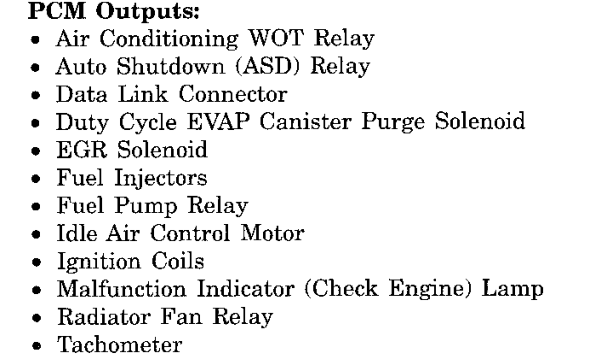
            s->flags_d1 &= 0x7Fu;
            s->engine_running_timer_96 = 0;
        }
    } else if (rpm_word < state_be16(cal + 2)) {
        s->flags_d1 &= 0xBFu;
        s->flags_d1 |= VIPER_STARTUP_FUEL_PHASE;
        s->transient_c4 = 0;
        s->run_events_b6 = 0;
        s->coolant_at_start_a7 = coolant;
        return true; 
    }
    return false;
}
void viper_post_crank_latch_fragment(uint16_t rpm_word, uint16_t incoming_d_word,
                                    const uint8_t cal[11],
                                    ViperEngineState *s)
{
    if ((s->flags_d1 & VIPER_SPARK_STARTUP_PHASE) != 0) {
        if (rpm_word < state_be16(cal + 4)) {
            s->post_crank_delay_b7 = cal[8];
            return;
        }
        if (s->post_crank_delay_b7 != 0) {
            --s->post_crank_delay_b7;
            if (s->post_crank_delay_b7 != 0) return;
        }
        s->flags_d1 |= VIPER_POST_CRANK_QUALIFIED | VIPER_SPARK_RUNUP_PENDING;
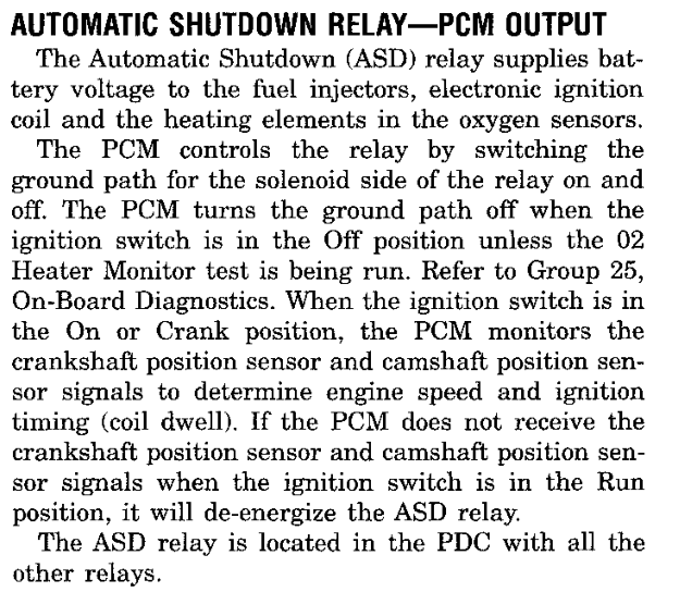
        s->flags_d1 &= 0xDFu;
    } else if (incoming_d_word < state_be16(cal + 6)) {
        s->flags_d1 &= 0xEFu;
        s->flags_d1 |= VIPER_SPARK_STARTUP_PHASE;
        s->flags_d5 |= VIPER_SPARK_INIT_SENTINEL;
    }
}
Fig. 3 Running Latch and Post-Crank Qualification

EVENT WORK REQUESTS

For each waiting event, the engine-speed routine reads the event entry and sets pending-work bits in F80D2 (Fig. 4). The phase flags choose between the startup and the ordinary calculations. The pending-work dispatcher (028992) takes the lowest set bit, clears it, calls its handler through the table at ROM 0478, and scans again until no bit remains. Pending bits combine: one bit can stand for several events.

EVENT ENTRY TO PENDING WORK · 026CFCrequest bits
026E84LDAB  E,IX; event entry026E86BITB  #0x10026E88BEQ   0x026e8e026E8ABSET  0xd2,Z,#0x4; history work026E8EBITB  #0x1026E90BEQ   0x026ea2026E92BRCLR 0xd1,Z,#0x20,0x026e9e; test F80D1.20026E98BSET  0xd2,Z,#0x10; spark initialization026E9CBRA   0x026ea2026E9EBSET  0xd2,Z,#0x2; ordinary spark026EA2BITB  #0x2026EA4BEQ   0x026eb6026EA6BRCLR 0xd1,Z,#0x80,0x026eb2; test F80D1.80026EACBSET  0xd2,Z,#0x8; startup fuel026EB0BRA   0x026eb6026EB2BSET  0xd2,Z,#0x1; ordinary fuel
Fig. 4 Event Entry Bits Set Pending Work
Fig. 5 Engine Event Path
PENDING BITHANDLERWORK
010109DCFuel calculation
0201015ASpark calculation
04016A36Event-interval history
08011B14Startup fuel calculation
100100E8Spark initialization

The fuel calculation stores two prepared values, group A in F82B0 and group B in F82B2. Below 5500 rpm the fuel calculation sends its own command 13. At or above that speed, the capture interrupt sends the prepared value itself on each event whose entry carries bit 40, choosing the group with bit 20. Fuel amount is described in 3-1 Fuel Amount.

FIRING ORDER AND CYLINDER OUTPUTS

At reset (020000) the PCM reads the engine profile selector at ROM 2707. Value 02 selects the V10 profile at ROM 06CA and the fuel mask table at ROM 08BA, and their pointers are saved in F8058 and F8177.

The cylinders are numbered front to rear, 1, 3, 5, 7, 9 on the left bank and 2, 4, 6, 8, 10 on the right bank. The firing order is 1, 10, 9, 4, 3, 6, 5, 8, 7, 2 (Fig. 6). The profile stores this order at ROM 06E4 as cylinder indexes counted from zero (Fig. 7).

Cylinders numbered front to rear, 1-3-5-7-9 left bank and 2-4-6-8-10 right bank; firing order 1, 10, 9, 4, 3, 6, 5, 8, 7, 2
Fig. 6 Cylinder Numbering and Firing Order (Group 9)
V10 FIRING-ORDER SEQUENCErecords
POSITIONSTORED CYLINDER INDEXCYLINDER NUMBER
001
1910
289
334
423
556
645
778
867
912

ROM 0006E4–0006ED · 10 bytes

Fig. 7 V10 Firing-Order Sequence — complete entry 9-6, Fig. 4

The ten fuel-output masks at ROM 08BA follow the same sequence, rotated by one position. The normal and startup fuel calculations index the masks with the fuel cursor F811E and test the selected mask against the fuel inhibit words F8179 and F817B, and a match zeroes the prepared fuel value. The capture routine sets the cursor when it synchronizes the event index and returns it to zero when the index wraps.

TEN FUEL-OUTPUT MASKSrecords
SLOTMASK (HEX)ONE-BASED BIT
0020010
101009
200084
300043
400206
500105
600808
700407
800022
900011

ROM 0008BA–0008CD · 20 bytes · Read by 0109DC

Fig. 8 Fuel-Output Masks — complete entry 9-6, Fig. 6

The ignition system uses two coil packs: three coils in the left pack fire cylinders 1, 2, 3, 4, 6 and 7, and two coils in the right pack fire cylinders 5, 8, 9 and 10. Each coil fires two cylinders at once, one on its compression stroke and the other on its exhaust stroke (Fig. 9). In the firing order, the two cylinders of one coil are five positions apart: 1 and 6, 10 and 5, 9 and 8, 4 and 7, 3 and 2.

The five cylinder-pair masks at ROM 08CE use the same spacing. Each mask joins two fuel-mask bits that sit five firing positions apart. The inhibit-mask merge (01F874) adds the selected pair masks to the inhibit word F817B; together the five masks cover all ten bits.

Two epoxy-filled coil packs on the rear of the engine; the left pack fires cylinders 1, 2, 3, 4, 6 and 7, the right pack fires 5, 8, 9 and 10
Fig. 9 Ignition Coil — PCM Output (Group 14)
Each coil fires two cylinders at once, one on compression and one on exhaust; the PCM grounds each coil and determines cylinder identification from the crankshaft and camshaft position sensors
Fig. 10 Ignition Coil — PCM Output (continued) (Group 14)
CYLINDER-PAIR INHIBIT MASKSrecords
PAIRMASK (HEX)ONE-BASED BIT POSITIONS
000211 / 6
102105 / 10
201808 / 9
300484 / 7
400062 / 3

ROM 0008CE–0008D7 · 10 bytes · Read by 01E03C

Fig. 11 Cylinder-Pair Inhibit Masks — complete entry 9-6, Fig. 7

DIAGNOSIS AND TESTING

ENGINE POSITION TROUBLE CODES

The service manual lists two trouble codes for the engine position inputs (Fig. 12, Fig. 13). The PCM code catalog at ROM 1222 holds both. Its record number matches the manual's hex code, and each record carries the generic code and the blink code.

Trouble code row: hex 01, MIL code 54, P0340, no cam signal at PCM, no camshaft signal detected during engine cranking
Fig. 12 No Cam Signal at PCM (Group 25)
Trouble code row: hex 28, MIL code 11, no crank reference signal at PCM, no crank reference signal detected during engine cranking
Fig. 13 No Crank Reference Signal at PCM (Group 25)
RECORDGENERIC CODEBLINK CODECONDITION
01P034054No cam signal at PCM
28P032011No crank reference signal at PCM

Fault reporting is described in 8-2 Fault Reporting.

SPECIFICATIONS

DESCRIPTIONSPECIFICATIONROM
Engine profile selector (V10)022707
Events per index cycle2006CD
Event index set when port bit 08 is set / clear10 / 006CB–06CC
Engine speed constant, high / low word2DC6 C00006CE
Speed measured across2 events0703
Engine-running flag sets at or above400 rpm2600
Engine-running flag clears below150 rpm2602
Post-crank qualification speed450 rpm2604
Post-crank qualifying passes42608
Spark-initialization return value (register D)04B02606
Interrupt fuel send at or above5500 rpm2138
Event watchdog reloads73 / 80 counts2100–2101

Engine speed words convert at 8 counts per rpm. Firing order 1-10-9-4-3-6-5-8-7-2.

CIRCUITPCM CAVITYFUNCTION
K32C3-1Ignition coil 4 driver
K18C3-3Ignition coil 3 driver
K43C3-5Ignition coil 5 driver
K19C3-7Ignition coil 1 driver
K24C3-8Crankshaft position sensor signal
K17C3-9Ignition coil 2 driver
K44C3-18Camshaft position sensor signal

CALIBRATION STRUCTURES

STRUCTUREROMTYPEREFER TO
Selected V10 engine profile0006CArecords9-6, Fig. 3
Running entry threshold002600setting9-3, Fig. 1
Running exit threshold002602setting9-3, Fig. 2
Post crank qualification threshold002604setting9-3, Fig. 3
Post crank reset live D threshold002606setting9-3, Fig. 4
Post crank qualifying visits002608setting9-3, Fig. 5
Throttle duration strict threshold002609setting9-3, Fig. 6
Startup delay value00260Asetting9-3, Fig. 7
Off idle return margin002614setting9-3, Fig. 8
Off idle entry margin002615setting9-3, Fig. 9
Larger opening margin002617setting9-3, Fig. 10
Larger opening threshold cap00261Asetting9-3, Fig. 11
Engine-speed threshold words002649records9-6, Fig. 11
Engine profile selector002707records9-6, Fig. 12
Post start coolant lower inclusive002771setting9-3, Fig. 12
Post start coolant upper exclusive002772setting9-3, Fig. 13
Post start countdown normal002773setting9-3, Fig. 14
Post start hot threshold002774setting9-3, Fig. 15
Post start countdown hot002775setting9-3, Fig. 16
Closed throttle spark RPM highbyte limit002776setting9-3, Fig. 17
Fixed spark during combined modes002777setting9-3, Fig. 18
Alternative engine structure 100C2BErecords9-6, Fig. 14
Alternative engine structure 200C312records9-6, Fig. 15
Alternative engine structure 300C366records9-6, Fig. 16
Alternative engine structure 400C3BArecords9-6, Fig. 17
Selected engine-dependent structure00C40Erecords9-6, Fig. 18
2 - 22 · ENGINE EVENTSSR

LOSS OF ENGINE EVENTS

DESCRIPTION AND OPERATION

ENGINE EVENT WATCHDOGS

The PCM confirms that the engine is turning by watching for engine events. Each event enters the engine event capture interrupt (028F24), which records the event timing, marks event activity and reloads two watchdog counters: F80C7 from 80 counts and F80C6 from 73 counts. While events keep arriving, both counters are refilled before they run out (Fig. 1). Engine position and the event pattern are described in 2-1 Engine Position and Timing.

The watchdog check (013E3E) runs in the fast job schedule through 01FCBC, which releases it every 22 scheduler ticks (1-3 Job Scheduling). Counter values are counts of these checks. The two counters expire on different boundaries:

  • F80C7, immediate path. Each check decrements a non-zero F80C7. The check that takes it from 1 to 0 performs loss handling at once.
  • F80C6, armed path. This path arms only while the engine running flag F80D1.40 is set and the high byte of the runtime word F8096 has reached 4. The check then sets the arm flag F80CE.01. An armed check decrements a non-zero F80C6 and returns. The next armed check that finds F80C6 already at zero performs loss handling.

The readable C in Fig. 2 matches the original instructions in every one of 3,072 checked cases.

1 → 0armedENGINE EVENT CAPTUREreload F80C6 · F80C7WATCHDOG CHECKfast schedule · every 22 ticksF80C7 REACHES ZEROloss on the same checkARMED F80C6 AT ZEROloss on the next checkRETIRE RUNNING STATEclear speed words · clear F80D1.40LOSS OUTPUT TAIL013DD6 · set F8106.C0OUTPUT COMMANDS2D payload 64 · 04 with F8106
Fig. 1 Engine Event Watchdog Path

RUNNING STATE RETIREMENT

Both expiry paths retire the running state so that other jobs stop treating the engine as turning. Each path clears the engine speed words F805A–F805D, the runtime word F8096 and F817D, clears the running flag F80D1.40 together with F80D1.10, and sets F80D1.80 and F80D1.20. Each path also clears the event state bits F80CE.20 and F80CE.10 and the bits F80CF.02 and F80CF.01.

The paths differ in detail. The immediate path also clears the spark target F83D5, the delivered spark value F83D6 and the final spark value F83D9 (4-1 Spark Timing), and clears F80CF.08 and sets F8847.80 only when F80CE.20 or F80CE.10 was set. The armed path first saves the high byte of F8096 to F899F, clears its own arm flag F80CE.01, and always clears F80CF.08 and sets F8847.80. Both paths then jump to the shared loss output tail at 013DD6.

Because F80CE.10 is cleared, the next engine event is handled as a first event. That branch of the capture interrupt restores the output requests, as described under Recovery.

READABLE Cviper_event_watchdogs.c
enum viper_event_result viper_expire_engine_event_watchdogs(uint8_t *r,
                                                          uint8_t threshold)
{
    if (r[0xC7] != 0) {
        uint8_t remaining = (uint8_t)(r[0xC7] - 1);
        if (remaining == 0) {
            r[0x17D] = r[0x96] = r[0x97] = 0;
            if ((r[0xCE] & 0x30) != 0) {
                r[0xCF] &= (uint8_t)~0x08;
                r[0x847] |= 0x80;
            }
            r[0x5A] = r[0x5B] = r[0x5C] = r[0x5D] = 0;
            r[0x3D6] = r[0x3D5] = r[0x3D9] = 0;
            r[0xCE] &= (uint8_t)~0x30;
            r[0xCF] &= (uint8_t)~0x03;
            r[0xD1] = (uint8_t)((r[0xD1] & ~0x50) | 0xA0);
            r[0xC7] = 0;
            return VIPER_EVENT_LOSS_TAIL;
        }
        r[0xC7] = remaining;
    }
    if ((r[0xD1] & 0x40) != 0 && (r[0xCE] & 1) == 0 && r[0x96] >= threshold)
        r[0xCE] |= 1;
    if ((r[0xCE] & 1) == 0)
        return VIPER_EVENT_RETURN;
    if (r[0xC6] != 0) {
        --r[0xC6];
        return VIPER_EVENT_RETURN;
    }
    r[0x99F] = r[0x96];
    r[0x17D] = r[0x96] = r[0x97] = 0;
    r[0x5A] = r[0x5B] = r[0x5C] = r[0x5D] = 0;
    r[0xCE] &= (uint8_t)~0x31;
    r[0xCF] &= (uint8_t)~0x0B;
    r[0xD1] = (uint8_t)((r[0xD1] & ~0x50) | 0xA0);
    r[0x847] |= 0x80;
    return VIPER_EVENT_LOSS_TAIL;
}
Fig. 2 Engine Event Watchdog Expiry (readable C, offsets from F8000)

LOSS OUTPUT REQUESTS

The service manual states that the Automatic Shutdown (ASD) relay supplies battery voltage to the fuel injectors, ignition coils and oxygen sensor heaters, and that the PCM de-energizes the ASD relay when it does not receive the crankshaft and camshaft position signals with the ignition switch in Run (Fig. 3). With the key on and the engine not running, the ASD and fuel pump relays de-energize after approximately 1 second (Fig. 5).

In the software, the loss output tail at 013DD6 turns the loss into output requests (Fig. 4). If F8106.40 is already set, the loss requests are already in place and the tail returns. Otherwise it sets request bits F8106.80 and F8106.40, sets F848E.20, and sets F8108.04 because ROM 2708 bit 40 is clear in this image (08). It then queues output command 2D with payload 64 and output command 04 carrying the F8106 request byte, and copies F8106 to its shadow F8103 so that the changed-output service (029AFC) does not send it again. When F8541.10 is set, the tail sends command 04 only. When F851E holds EC13 with F8522.04 and F853F.20 set, the tail skips the request bits and sends the two commands directly. The DRB ASD relay test toggles the same bit, F8106.40 (see Diagnosis and Testing). Output commands are described in 5-1 Output Commands.

ASD relay supplies the injectors, ignition coils and oxygen sensor heaters; the PCM switches the relay ground and de-energizes the relay without crankshaft and camshaft position signals in Run
Fig. 3 Automatic Shutdown Relay — PCM Output (Group 14)
EVENT-LOSS OUTPUT SERVICE · 013D90complete routine
013D90BRSET 0x128,Z,#0x8,0x013e3c; diagnostic mode013D96BRSET 0x497,Z,#0x80,0x013da8; recovery013D9CBRSET 0xd1,Z,#0x40,0x013da8; running013DA2LDAA  0xc7,Z; F80C7 expired013DA6BEQ   0x013dd6013DD6LDD   0x51e,Z; EC13 test state013DDACPD   #0xec13013DDEBNE   0x013dec013DE0BRCLR 0x522,Z,#0x4,0x013dec013DE6BRSET 0x53f,Z,#0x20,0x013e0a013DECBRSET 0x106,Z,#0x40,0x013e3c; latched013DF2BSET  0x106,Z,#0xc0; set F8106.C0013DF6BSET  0x48e,Z,#0x20013DFABRSET 0x2708,#0x40,0x013e04; ROM 2708.40013E00BSET  0x108,Z,#0x4; set F8108.04013E04BRSET 0x541,Z,#0x10,0x013e1e013E0ALDAB  #0x64; payload 64
Fig. 4 Scheduled Entry and Loss Output Tail

SCHEDULED LOSS SERVICE

The event-loss output service (013D90) also runs on its own, every 1953 ticks in the slow job group (1-3 Job Scheduling). It does nothing while the diagnostic-mode bit F8128.08 is set. While the engine running flag F80D1.40 or F8497.80 is set, or while F80C7 is still counting, it enters the recovery gate. When F80D1.40 and F8497.80 are clear and F80C7 has reached zero, it enters the loss output tail. This service keeps the loss requests in force after the watchdogs have expired, and clears them through the recovery gate once F80D1.40 or F8497.80 is set or F80C7 is reloaded.

With the key on and zero rpm, the ASD and fuel pump relays de-energize after approximately one second
Fig. 5 Ignition Switch On (Zero RPM) Mode (Group 14)

RECOVERY

Two paths remove the loss requests. The service manual states that the PCM energizes the ASD and fuel pump relays after it receives the camshaft and crankshaft position signals (Fig. 6).

During start-up the PCM energizes the ASD and fuel pump relays after it receives the camshaft and crankshaft position sensor signals, and does not energize them if both signals are not received within approximately one second
Fig. 6 Engine Start-Up Mode (Group 14)
The ASD and fuel pump relays supply battery voltage to the fuel pump, fuel injectors, ignition coil and heated oxygen sensors
Fig. 7 Engine Start-Up Mode (continued) (Group 14)

First engine event. When an event arrives with F80CE.10 clear, the capture interrupt sets F80CE.90, clears F8106.40 and F8106.80, and clears F8108.04. It sends output command 04 with F8106 and copies the byte to its shadow. When F80E4 is below 9 it queues command 2D with payload 60, and otherwise it sets F80CC.02. When F80CC.40 is set, it sets F80CC.02 and sends neither command.

Recovery gate. The gate (013DA8) returns at once when F8106.40 is already clear. Otherwise the recovery commands (013DAE) clear F8106.C0 and F8108.04, load F80C7 with 5 so that the immediate watchdog expires again unless events refresh it, queue command 2D with payload 60, and send command 04 with F8106. When F851E holds EC13 with F8522.04 set, the recovery commands skip the F80C7 reload and the command 2D request.

RECOVERY COMMANDS · 013DAEdecisive instructions
013DAEBCLR  0x106,Z,#0xc0; clear F8106.C0013DB2BRSET 0x2708,#0x40,0x013dbc013DB8BCLR  0x108,Z,#0x4; clear F8108.04013DCCLDAA  #0x5; F80C7 = 5013DCESTAA  0xc7,Z013DD2LDAB  #0x60; payload 60
Fig. 8 Recovery Requests and Watchdog Reload
REQUESTLOSSRECOVERY
F8106.80, F8106.40SetCleared
F8108.04SetCleared
Command 2D payload6460
Command 04F8106F8106

DIAGNOSIS AND TESTING

DRB OUTPUT TESTS

Three DRB tests operate the same requests and commands as the loss and recovery paths. Each test is reached through the SCI diagnostic table.

DRB TESTSCIROUTINESHARED WITH
ASD relay13-0A00E4F0Toggles F8106.40
ASD fuel system13-1C00E842Command 2D, payload 60 or 64
Fuel-system relay13-3300EA0CF80D7.02; command 2D, payload 60 or 64
CAUTION: The service manual states that during the ASD Fuel System Test the ASD relay and fuel pump relay remain energized for 7 minutes, until the test is stopped, or until the ignition switch is turned Off.

DIAGNOSTIC TROUBLE CODES

The service manual lists the following codes for the signals and relay circuits in this section.

HEXBLINKP CODEDESCRIPTION
2811No crank reference signal at PCM
0154P0340No cam signal at PCM
9D11P1391Intermittent loss of CMP or CKP
0A42Auto shutdown relay control circuit
6542Fuel pump relay control circuit

Service manual group 25, pages 25-3 to 25-6. Fault reporting is described in 8-2 Fault Reporting.

SPECIFICATIONS

DESCRIPTIONSPECIFICATIONROM
Immediate watchdog F80C7 reload at each engine event80 counts2101
Armed watchdog F80C6 reload at each engine event73 counts2100
Armed path enable, runtime word high byte at or above42103
Configuration byte (bit 40 clear: F8108.04 follows loss and recovery)082708
Watchdog check interval22 ticks08DC
Loss output service interval1953 ticks090A

Watchdog counts are counts of watchdog checks.

ASD relay coil ground on K51 at PCM cavity C3 (gray connector C1-3); relay output A142 feeds injectors, ignition coils and generator and returns to PCM cavity C12 as the ASD energized signal
Fig. 9 Automatic Shut Down Relay Circuit (Group 8W-30)
CIRCUITPCM CAVITYFUNCTION
K51C1-3Automatic shutdown (ASD) relay control
A142C1-12ASD relay output / PCM sense
K31C1-19Fuel pump relay control
SR3 · FUEL SYSTEM3 - 1

FUEL AMOUNT

DESCRIPTION AND OPERATION

FUEL CALCULATION

The PCM controls injector pulse width by switching the ground path to each injector. Engine speed and manifold absolute pressure are the primary inputs that determine pulse width (Fig. 1). The PCM software follows the same plan: a base quantity is read from a speed-by-pressure map, corrected, tested against the fuel-cut requests and handed to the output command path as a raw fuel word (Fig. 2).

Two routines calculate fuel. Each engine event whose profile entry carries bit 02 sets a pending task, and the task dispatcher (028992) runs one of them. While the startup-fuel phase flag F80D1 bit 80 is set, the event schedules the startup fuel routine (011B14). Once the engine-running latch clears that phase, the same event schedules the running fuel routine (0109DC). Engine events and the running latch are described in 2-1 Engine Position and Timing.

The startup routine builds its quantity F82AE from a coolant curve, a pressure correction, a correction against an event counter and a speed correction, then sends it through the same fuel command as the running routine.

Service manual text: the PCM adjusts injector pulse width by switching the injector ground path; engine RPM and manifold absolute pressure are the primary inputs
Fig. 1 Injector Pulse Width (Group 14)
Fig. 2 Running Fuel Calculation Path

BASE FUEL MAP

The running fuel routine converts its two inputs into map coordinates. The engine speed word F805A is rounded to its high byte and normalized through the engine speed axis at ROM 2814 into F8170. The filtered manifold pressure byte F804E is normalized through the pressure axis at ROM 284A into F816F. The word-grid lookup (029EB2) then interpolates the selected map between its four surrounding cells and stores the base fuel word in F82A0 (Fig. 3).

The map holds 17 engine speed rows by 9 pressure columns of 16-bit cells. Interpolation is integer arithmetic: each coordinate is scaled by the table dimension less one, the high byte selects the cell and the low byte is the fraction. Each of the two bounding rows is interpolated and rounded, then the two results are interpolated and rounded again. The lookup method is described in 9-2 Fuel and Starting Tables.

Two base fuel maps are present, A at ROM 2B82 and B at ROM 2CB8. Map B is selected when either bit of mask 14 in F80CB is set and both bits of mask 05 in F880B are clear; otherwise map A is selected. In this calibration the two maps hold identical values, so the selection does not change the base fuel word.

RUNNING FUEL CALCULATION · 0109DCmap select and lookup
011218LDX   #0x2b82; map A01121CBRCLR 0xcb,Z,#0x14,0x011232; mode bits 14011222BRSET 0x80b,Z,#0x4,0x011232; F880B bit 04011228BRSET 0x80b,Z,#0x1,0x011232; F880B bit 0101122ELDX   #0x2cb8; map B011232LDAA  0x170,Z; speed coordinate011236LDAB  0x16f,Z; pressure coordinate01123AJSR   0x01003c; word grid lookup01123ESTE   0x2a0,Z; base fuel word
Fig. 3 Base Fuel Map Selection and Lookup
BASE FUEL Agrid

raw counts · Rows: Engine speed axis (9-7, Fig. 4) · Columns: Manifold pressure axis (9-7, Fig. 5)

012345678
01061602565287681056155221923584
11061604165608321136170423043584
21062564325608001312176823843232
31063204325608961376184024163168
41083204806089441424185624163168
511032051264010241472190424003136
612133654473610561520195224803136
715142457678412321680216026883280
824749669697614081872236828803440
9257544760102414721952241629123472
1024049672099214561920240029123504
11355619941113616162144265632483808
124467181000131218242336286434564016
13442700987131218242320284835844096
14410668968128018002304284836164192
15384636952124817762288283236164288
16356604936121617522272281636004288

Point to a cell for its ROM address and stored value.

ROM 002B82–002CB7 · 310 bytes · Read by 0109DC

Fig. 4 Base Fuel Map A (Map B at 2CB8 is identical) — complete entry 9-2, Fig. 1

FUEL CORRECTIONS

The running routine applies a series of calibrated corrections to the base word. An intake air temperature curve (ROM 2E01) produces F826B. The enrichment grid at ROM 2E4F, indexed by the same speed and pressure coordinates, supplies an enrichment factor; a second enrichment curve against engine speed (ROM 2F11) serves an alternate path. The bank 1 and bank 2 oxygen-feedback routines (011DF0, 0128CA) maintain the short-term and long-term trims. The running routine applies the bank 1 or bank 2 trims according to the active fuel group, F80BC bit 20. Fuel feedback is described in 3-2 Fuel Feedback.

An injector offset is added to the fuel quantity. The fuel timer service (013426) reads the offset curve at ROM 2DEE into F826F, multiplies the result by four and adds the signed base offset at ROM 2B75. The sum saturates at the signed 16-bit limits and is stored in F82B4 (Fig. 5). The running routine adds F82B4 to the fuel quantity. A separate service (01365C) sends the curve byte F826F on select 1D when the command queue has room.

The prepared value is then held at no less than the fuel floor at ROM 2B79 before the fuel-cut gates are tested.

READABLE Cviper_fuel_ignition.c
int16_t viper_compute_injector_offset(uint8_t curve_result, int16_t base_offset)
{
    int32_t sum = (int32_t)curve_result * 4 + base_offset;
    if (sum > INT16_MAX) return INT16_MAX;
    if (sum < INT16_MIN) return INT16_MIN;
    return (int16_t)sum;
}
Fig. 5 Injector Offset Arithmetic

DECELERATION FUEL CUT

During a hard deceleration with a closed throttle, the PCM momentarily turns off the injectors (Fig. 6). The cut-request routine (0134A6) decides when to latch this condition, and the running fuel routine decides when to release it (Fig. 7).

Entry is qualified first. The high byte of the engine-running timer F8096, the pressure value F8804, intake air temperature, the vehicle speed byte and coolant temperature must each be at or above its calibrated minimum. Engine speed must then be strictly above the idle speed target F811C plus the entry margin. The margin is read from the curve at ROM 390E against coolant temperature; refer to Specifications.

When the throttle is off idle (F80D6 bit 80), the routine reloads the entry delay F82D7. At closed throttle, the working fuel word for the active group must be below the entry fuel ceiling and the re-entry lockout F80B3 must be zero. Each qualifying pass then decrements the entry delay. The pass that finds the delay already at zero sets the deceleration cut flag F82D3 bit 10, sets its mirrored request F82D6 bit 10 and loads the hold count F829C (Fig. 8).

While the latch is set, the running fuel routine saves the prepared fuel word and tests three resume conditions: engine speed at or below the idle target plus the resume margin from the curve at ROM 392A, the throttle off idle, or the working fuel word for the active group at or above the resume fuel threshold. Any one condition clears both flags, sets spark flag F80D4 bit 01, reloads the re-entry lockout F80B3 and restores the saved fuel word. Otherwise the fuel word is set to zero for that pass.

A temporary deceleration profile with its own entry and resume curves (ROM 8069 and 8085) is selected by F883B bit 80. The reset routine enables it only when ROM 8068 bit 80 is set; that byte is 00 in this calibration.

Service manual text: deceleration mode inputs; a closed-throttle input with an abrupt decrease in manifold pressure indicates a hard deceleration, and the PCM momentarily turns off the injectors
Fig. 6 Deceleration Mode (Group 14)
noyesnoyesENTRY QUALIFICATIONtimer · pressure · IAT · speed · coolantengine speed above idle + curve 390ECLOSED THROTTLE?F80D6 · bit 80RELOAD DELAYF82D7 ← ROM 395FFUEL BELOW CEILINGROM 394F · lockout F80B3 zeroDELAY AT ZERO?F82D7COUNT DOWNF82D7 − 1DECEL CUT LATCHEDF82D3.10 · F82D6.10 · fuel word zeroRESUME TESTspeed ≤ idle + curve 392Athrottle off idle · fuel ≥ ROM 3951
Fig. 7 Deceleration Fuel Cut Latch
READABLE Cviper_fuel_cut.c
bool viper_qualify_decel_cut_fragment(uint8_t throttle_flags, uint8_t group_flags,
    uint16_t fuel_a, uint16_t fuel_b, const ViperFuelCutCalibration *cal,
    ViperFuelCutState *s)
{
    bool alternate = (s->override_flags & 0x80u) != 0;
    uint16_t fuel = (group_flags & 0x20u) != 0 ? fuel_b : fuel_a;
    if ((throttle_flags & 0x80u) != 0) {
        s->entry_delay = alternate ? cal->alternate_entry_delay_reload
                                  : cal->entry_delay_reload;
        return false; 
    }
    if (fuel >= (alternate ? cal->alternate_entry_fuel_limit
                           : cal->entry_fuel_limit) || s->reentry_lockout != 0)
        return false;
    if (s->entry_delay != 0) {
        --s->entry_delay;
        return true; 
    }
    s->flags_d3 |= 0x10u;
    s->requests_d6 |= 0x10u;
    s->hold_29c = cal->hold_reload;
    return true;
}
Fig. 8 Deceleration Cut Latch at Closed Throttle
DECEL CUT ENTRY RPM MARGIN VS COOLANTcurve
0 → 92180 → 921Temperature 0–80 °CEngine speed 921 RPM
Points (2)
TEMPERATURE (°C)ENGINE SPEED (RPM)
0921
80921

ROM 00390E–003914 · 7 bytes · Read by 0134A6, 029DD6

Fig. 9 Deceleration Cut Entry Margin — complete entry 9-2, Fig. 15
DECEL CUT RESUME RPM MARGIN VS COOLANTcurve
0 → 88080 → 880Temperature 0–80 °CEngine speed 880 RPM
Points (2)
TEMPERATURE (°C)ENGINE SPEED (RPM)
0880
80880

ROM 00392A–003930 · 7 bytes · Read by 0109DC, 029DD6

Fig. 10 Deceleration Cut Resume Margin — complete entry 9-2, Fig. 16

ENGINE SPEED LIMITS AND FUEL DELIVERY

The same routine maintains two speed-limit requests. The engine speed limit sets F82D3 bit 01 and request F82D6 bit 40 when engine speed exceeds the limit at ROM 3955. While the request is set, the limit is lowered by the release drop at ROM 3953, so the request clears only when speed falls to the lower value. When status bit F8808 bit 20, F8808 bit 40 or F8809 bit 20 is set, the limit is taken from ROM 6009 instead, with the same release drop (Fig. 11).

The combined limit sets F82D3 bit 02 and request F82D6 bit 80 only when engine speed exceeds the limit at ROM 3959 and the filtered road speed word F8135 exceeds the limit at ROM 395B. Both limits drop by their release values while the request is set.

The running fuel routine sets the prepared fuel word to zero whenever F82D3 bit 01 or bit 02 is set, or when external status bit F865E bit 20 or F8584 bit 20 is set. Bit 20 of F80BC selects the group fuel word, F82B0 or F82B2, that receives the result. The other group word receives the same value while its counter (F8296 for F82B0, F8297 for F82B2) is zero; ROM 270D bit 01 suppresses this copy, and that byte is 00 in this calibration. Below the engine speed threshold at ROM 2138, the running routine queues fuel command 13 on select 1D itself. At and above that threshold, the engine-event interrupt (028F24) queues the same command from the stored word of the active group whenever F80BC bit 40 is set. The command queue is described in 5-1 Output Commands. The PCM grounds the ten injector drivers in sequence (Fig. 12).

CUT REQUEST UPDATE · 0134A6engine speed limit
0135F8BRSET 0x808,Z,#0x20,0x013610; status bits0135FEBRSET 0x809,Z,#0x20,0x013610013604BRSET 0x808,Z,#0x40,0x01361001360ALDD   0x3955; ordinary limit01360EBRA   0x013616013610LDAA  0x6009; status-selected limit013614CLRB  013616BRCLR 0x2d3,Z,#0x1,0x01362401361CSUBD  0x3953; release drop013620BCC   0x013624013622CLRD  013624CPD   0x5a,Z; engine speed013628BCS   0x01363401362ABCLR  0x2d3,Z,#0x1; clear request01362EBCLR  0x2d6,Z,#0x40013632BRA   0x01363c013634BSET  0x2d3,Z,#0x1; set request013638BSET  0x2d6,Z,#0x4001363CRTS   
Fig. 11 Engine Speed Limit with Release Drop
Service manual text: the ASD relay supplies battery voltage to the injectors and the PCM switches each injector ground path, energizing the injectors sequentially
Fig. 12 Fuel Injectors — PCM Output (Group 14)

SPECIFICATIONS

DESCRIPTIONSPECIFICATIONROM
Fuel command passed to engine-event interrupt at or above5500 rpm2138
Prepared fuel floor445 counts2B79
Injector offset base value179 counts2B75
Decel entry, running timer high byte at least10 counts3946
Decel entry, pressure value F8804 at least128 counts394A
Decel entry, intake air temperature at least-50 °C3947
Decel entry, vehicle speed byte at least64 counts3948
Decel entry, coolant temperature at least60 °C3949
Decel entry margin above idle target (0 °C and 80 °C)921 rpm390E
Decel entry fuel word ceiling864 counts394F
Decel entry delay reload255 passes395F
Decel hold count reload91 counts334C
Decel resume margin above idle target (0 °C and 80 °C)880 rpm392A
Decel resume fuel word threshold1024 counts3951
Decel re-entry lockout reload254 counts394B
Engine speed limit, request sets above6200 rpm3955
Engine speed limit release drop400 rpm3953
Status-selected engine speed limit3200 rpm6009
Combined limit, engine speed above7000 rpm3959
Combined limit, engine speed release drop400 rpm3957
Combined limit, road speed word above16320 counts395B
Combined limit, road speed release drop1920 counts395D

Engine speed words convert at 8 counts per rpm; a single speed byte converts at 32 rpm per count. Temperatures are the stored value minus 64 °C. Fuel words are raw counts.

CIRCUITPCM CAVITYFUNCTION
K26C2-2Injector 7 driver
K5C2-3Injector 9 driver
K11C2-4Injector 1 driver
K13C2-5Injector 3 driver
K38C2-6Injector 5 driver
K58C2-12Injector 6 driver
K28C2-13Injector 8 driver
K8C2-14Injector 10 driver
K12C2-15Injector 2 driver
K14C2-16Injector 4 driver

CALIBRATION STRUCTURES

STRUCTUREROMTYPEREFER TO
Base fuel a002B82grid9-2, Fig. 1
Base fuel b002CB8grid9-2, Fig. 2
Injector offset vs input002DEEcurve9-2, Fig. 3
Fuel intake-air temperature correction002E01curve9-2, Fig. 4
Fuel barometric correction002E14curve9-2, Fig. 5
Fuel pressure related reduction002E27curve9-2, Fig. 6
Fuel enrichment factor002E4Fgrid9-2, Fig. 7
Alternate fuel enrichment vs speed002F11curve9-2, Fig. 8
Startup fuel vs coolant002F49curve9-2, Fig. 9
Startup fuel barometric correction002F5Ccurve9-2, Fig. 10
Startup fuel counter correction002F6Fcurve9-2, Fig. 11
Startup fuel speed correction002F82curve9-2, Fig. 12
Fuel counter coolant strict min003349setting9-2, Fig. 13
Decel cut hold reload00334Csetting9-2, Fig. 14
Decel cut entry RPM margin vs coolant00390Ecurve9-2, Fig. 15
Decel cut resume RPM margin vs coolant00392Acurve9-2, Fig. 16
Decel entry running timer high min003946setting9-2, Fig. 17
Decel entry intake-air temperature min003947setting9-2, Fig. 18
Decel entry speed byte min003948setting9-2, Fig. 19
Decel entry coolant min003949setting9-2, Fig. 20
Decel entry baro byte min00394Asetting9-2, Fig. 21
Decel resume reentry lockout reload00394Bsetting9-2, Fig. 22
Decel entry fuel word ceiling00394Fsetting9-2, Fig. 23
Decel resume fuel word threshold003951setting9-2, Fig. 24
Rev limit release drop003953setting9-2, Fig. 25
Ordinary rev limit003955setting9-2, Fig. 26
Combined limit RPM release drop003957setting9-2, Fig. 27
Combined limit RPM003959setting9-2, Fig. 28
Combined limit road speed word00395Bsetting9-2, Fig. 29
Combined limit speed release drop00395Dsetting9-2, Fig. 30
Decel entry delay reload00395Fsetting9-2, Fig. 31
Status selected rev limit high byte006009setting9-2, Fig. 32
Temporary cut profile startup enable008068setting9-2, Fig. 33
Temporary decel cut entry RPM margin008069curve9-2, Fig. 34
Temporary decel cut resume RPM margin008085curve9-2, Fig. 35
Temporary cut profile timer reload0080A1setting9-2, Fig. 36
Temporary decel entry intake-air temperature min0080A2setting9-2, Fig. 37
Temporary decel entry speed byte min0080A3setting9-2, Fig. 38
Temporary decel entry coolant min0080A4setting9-2, Fig. 39
Temporary reentry lockout reload0080A5setting9-2, Fig. 40
Temporary entry fuel word ceiling0080A7setting9-2, Fig. 41
Temporary resume fuel word threshold0080A9setting9-2, Fig. 42
Temporary entry delay reload0080ABsetting9-2, Fig. 43
3 - 23 · FUEL SYSTEMSR

FUEL FEEDBACK

DESCRIPTION AND OPERATION

CLOSED LOOP FUEL CONTROL

In CLOSED LOOP modes the PCM fine-tunes injector pulse width from the upstream heated oxygen sensor inputs (Fig. 1). The software performs this work in two bank trim routines, one for each cylinder bank: 011DF0 for bank 1 and 0128CA for bank 2. Bank 1 reads its upstream oxygen value from F8038; bank 2 reads F803A.

The fuel pulse width routine (0109DC) calls both trim routines after it has selected the base fuel value (3-1 Fuel Amount). Each call is enabled by a configuration bit in ROM 270A: bit 80 enables the bank 1 routine and bit 20 enables the bank 2 routine (Fig. 2). This calibration stores A1, so both banks run. When RAM flag F8558 bit 10 is set, the bank 2 call also requires ROM 270D bit 40 to be clear; this calibration stores 00 at that address, so the call is always made.

Service manual text: open loop and closed loop modes; in closed loop the PCM monitors the upstream and downstream heated oxygen sensors and fine-tunes injector pulse width
Fig. 1 Modes of Operation (Group 14)
FUEL PULSE WIDTH · 0109DCtrim calls
0113C4BRCLR 0x270a,#0x80,0x0113ce; bank 1 enable0113CAJSR   0x011df0; bank 1 trim0113CEBRCLR 0x270a,#0x20,0x0113e4; bank 2 enable0113D4BRCLR 0x558,Z,#0x10,0x0113e00113DABRSET 0x270d,#0x40,0x0113e4; alternate layout0113E0JSR   0x0128ca; bank 2 trim
Fig. 2 Bank Trim Calls and Their Configuration Bits

The short-term correction for each bank is held in F828C (bank 1) and F828D (bank 2), and the long-term correction in F827E (bank 1) and F8280 (bank 2). The diagnostic data services report these four values as standard parameters 06 to 09, and report the two upstream oxygen values with their short-term corrections as parameters 14 and 18.

inhibitnoFUEL PULSE WIDTHcalls both bank routinesBANK TRIM ROUTINE011DF0 bank 1 · 0128CA bank 2CONFIGURATIONROM 270A · 270DLEARNING GATEinhibit F8880.02 · fault stateHEATER HISTORY019B54FEEDBACK CONDITIONSoxygen limit · engine speedFALLBACK PATHshort-term clearedOXYGEN COMPARISONcurve 3704 · switching targetsREAR TARGET01D386 · 01D67ESHORT-TERM CORRECTIONF828C · F828D · limited
Fig. 3 Fuel Feedback Path (one bank)

LEARNING GATE AND FEEDBACK CONDITIONS

Each bank trim routine opens with a learning gate (Fig. 4). The gate tests the shared upstream inhibit flag F8880 bit 02 together with stored fault-state fields at F880C, F880D and F880E. When the inhibit flag or a selected F880D bit is set, the routine sets its inhibit marker (F8175 bit 08 for bank 1, F8176 bit 08 for bank 2). On any gate condition, the routine clears the bank's 27 learned entries (F889A for bank 1, F88B5 for bank 2) and branches to its fallback path. The fallback path clears the short-term correction and resets the working terms of the bank.

BANK 1 FUEL TRIM · 011DF0learning gate
011E00LDAB  0x80c,Z; fault state011E04ANDB  #0xf8011E06BNE   0x011e1e011E08BRSET 0x80e,Z,#0x20,0x011e1e011E0EBRSET 0x880,Z,#0x2,0x011e1a; upstream inhibit011E14BRCLR 0x80d,Z,#0xaa,0x011e38011E1ABSET  0x175,Z,#0x8; inhibit marker011E1ELDY   #0x889a; learned entries011E22LDAB  #0xf011E24TBYK  011E26LDE   #0x1b; 27 bytes011E2ACLR   0x0,Y011E2CAIY   #0x1011E2ESUBE  #0x1011E32BNE   0x011e2a011E34LBRA  0x01231a; fallback path011E38BCLR  0x175,Z,#0x8; gate passed
Fig. 4 Learning Gate, Bank 1

With the gate passed, the routine qualifies the upstream oxygen value. A value below 3E (ROM 3348) reloads a holdoff count from ROM 334E (bank 2: ROM 334F). A value at or above the limit sends the routine to the fallback path once the holdoff count is zero.

Engine speed is tested next, with hysteresis. Above 3808 rpm the routine sets its speed flag (F82D4 bit 01 for bank 1, F82D5 bit 01 for bank 2) and takes the fallback path. The flag clears only after engine speed falls to 96 rpm below the limit. Further state tests follow. Most divert the routine to the fallback path; two of them instead load a fixed short-term correction from ROM 338D or ROM 3352 and reset the working terms.

SHORT-TERM CORRECTION

The qualified oxygen value is converted through the curve at ROM 3704, shared by both banks, and the result (F8292 for bank 1, F8293 for bank 2) is compared with the bank's switching targets. One of those targets is the rear target value F828E (bank 2: F828F), written by the rear target routines 01D386 and 01D67E. The outcome of the comparison is held in the bank's feedback state byte, F82D4 or F82D5. Bit 02 of F82D4 is the bank 1 feedback state that the purge oxygen sequence also reads (5-2 Accessory and Evaporative Outputs).

Normal rear feedback is enabled by ROM 270A bit 40 for bank 1 and bit 10 for bank 2. Both bits are clear in this calibration, so the rear target routines run their fallback target handling.

The short-term correction is the signed sum of three working terms, F82A2, F8290 and F8286. The third term is the difference of two working values multiplied by the gain in ROM 35A3. The sum is limited to the range set by ROM 35AC and ROM 35AE for bank 1, and ROM 35AD and ROM 35AF for bank 2, before it is stored (Fig. 5).

BANK 1 FUEL TRIM · 011DF0sum and limit
01227ELDAB  0x2a2,Z; term F82A2012282SXT   012284TDE   012286LDAB  0x290,Z; term F829001228ASXT   01228CADE   01228ELDAB  0x286,Z; term F8286012292SXT   012294ADE   012296TED   012298TSTA  01229ABPL   0x0122ac01229CCMPA  #0xff01229EBNE   0x0122a60122A0CMPB  0x35ac; lower limit0122A4BCC   0x0122b80122A6LDAB  0x35ac0122AABRA   0x0122b80122ACBNE   0x0122b40122AECMPB  0x35ae; upper limit0122B2BCS   0x0122b80122B4LDAB  0x35ae0122B8STAB  0x28c,Z; short-term correction
Fig. 5 Short-Term Correction Sum and Limit, Bank 1

OXYGEN SENSOR STATE AND HEATER HISTORY

Two jobs in the fast supporting group (01FCF6) maintain the oxygen sensor state that the trim routines and monitors consume (1-6 Supporting Jobs).

The threshold tracking routine (0163C6) watches the rear bank 1 input F803C. A reading below 3D sets low flag F8568 bit 40 once its holdoff count, reloaded from ROM 7B82 (2), has expired; a reading at or above the threshold clears the flag and reloads the count. While the engine is running, the routine latches a low-to-high crossing of each enabled input: a reading below 0F arms the crossing, and a later reading at or above 28 completes it (Fig. 6). The bank 1 upstream crossing is always tracked; the rear bank 1 crossing is enabled by ROM 270A bit 20, which is set in this calibration.

OXYGEN THRESHOLD STATEviper_oxygen_state.c
static void low_holdoff(uint8_t *r, unsigned input, unsigned timer, uint8_t bit)
{
    if ((r[0x568]&bit)!=0) {
        if (r[input]>=0x3D) {r[0x568]&=(uint8_t)~bit;r[timer]=2;}
    } else if (r[timer]!=0) {
        uint8_t remaining=(uint8_t)(r[timer]-1);
        r[timer]=(remaining&0x80)!=0?0:remaining;
    } else if (r[input]<0x3D) r[0x568]|=bit;
}
static void low_then_high(uint8_t *r, unsigned input, unsigned state,
                          uint8_t seen_low, uint8_t completed)
{
    if ((r[state]&completed)!=0) return;
    if ((r[state]&seen_low)==0) {
        if (r[input]>=0x0F) return;
        r[state]|=seen_low;
    }
    if (r[input]>=0x28) {
        r[state]|=completed;
        r[state]&=(uint8_t)~seen_low;
    }
}
void viper_track_oxygen_threshold_state(uint8_t *r,uint8_t config_a,uint8_t config_d)
{
    low_holdoff(r,0x3C,0x556,0x40);
    if ((config_a&0x10)!=0) low_holdoff(r,0x3E,0x557,0x20);
    if ((r[0xD1]&0x40)==0) return;
    low_then_high(r,0x38,0x37A,8,4);
    if ((config_a&0x20)!=0) low_then_high(r,0x3C,0x37A,2,1);
    if ((config_d&0x40)!=0) low_then_high(r,0x3E,0x379,0x10,8);
}
Fig. 6 Oxygen Threshold Crossings and Holdoff

The heater history routine (019B54) reads the stored history of the four oxygen sensor heater codes and sets two shared inhibit flags. The upstream heater codes, P0135 and P0155, set F8880 bit 02, which the learning gate of both bank trim routines tests. The downstream heater codes, P0141 and P0161, set F8880 bit 01, which the rear target routines test. The routine recognizes exact combined history patterns: on every pass it sets each flag when its pattern is recognized and clears it otherwise.

Wiring diagram 8W-30-13: left upstream sensor signal K241 to PCM C3-24, right upstream sensor signal K41 to PCM C3-26, sensor ground K4 to C3-4, heaters fed from ASD relay output A142
Fig. 7 Upstream Heated Oxygen Sensors (Group 8W-30)

The ASD relay supplies battery voltage to the upstream and downstream heated oxygen sensor heaters. The upstream sensor signals reach the PCM on circuits K241 and K41 (Fig. 7).

DIAGNOSIS AND TESTING

FUEL SYSTEM MONITOR

The fuel system monitor compares the short-term correction, combined with the long-term (adaptive) memory, against a limit (Fig. 8). In the software this is the rich/lean trim monitor 01C512, attached to descriptor C02E. It tests pressure, running and feedback state, then compares the signed long-term and short-term corrections of each bank (F827E with F828C, and F8280 with F828D) through staged countdowns. Its result bits 01, 02, 04 and 08 at F8157 select fault codes P0172, P0171, P0175 and P0174 through the code list at ROM 6DDE. The selector 0151D2 takes the lowest remaining result bit and returns its fault id for recording (8-2 Fault Reporting).

Service manual text: short-term corrections in injector pulse width from the O2S and long-term adaptive memory compared to a limit; MIL illuminates when the optimum ratio cannot be maintained
Fig. 8 DTC 51/52 — Fuel System Monitor (Group 25)
Trouble code table rows: P0172 and P0171 right rear fuel system rich and lean; P0175 and P0174 left front fuel system rich and lean
Fig. 9 Fuel System Trouble Codes (Group 25)

MONITOR DESCRIPTORS

The detailed fault-monitor descriptors (Fig. 10) decide which monitor families the PCM schedules (8-1 Diagnostic Overview). In this calibration the enable mask allows the fuel system monitor (C02E). The oxygen-response descriptors C066 (018078, codes P0133, P0153, P0139) and C082 (0183EE, codes P0139, P0159) are not allowed, so their routines are not scheduled.

DETAILED FAULT-MONITOR DESCRIPTORSrecords
RECORDHANDLERWORKING RAMCONFIGURATIONCONDITION LIST ACONDITION LIST BALLOWED BY MASK
00C020017F120F8506006F2C006023006060No
00C02E01C5120F8504006F2E0060F60061D3Yes
00C03C017F7A0F8505006F300062610062EENo
00C04A01BFB60F8507006F3200637C006431No
00C0580195E40F8508006F340064AB006574No
00C0660180780F8509006F360065EE0066CBNo
00C0740198960F850A006F38006C8D006D56No
00C0820183EE0F850B006F3A006B72006C13No
00C0900100B00F850C006F3C0067590067D2No
00C09E01D9F80F850D006F3E0069DF006AD0No
00C0AC01536A0F8515000000006DD0006DD0No
00C0BA0157EC0F850E006F4000684C00693DNo

1 more records in 9-5, Fig. 126

ROM 00C020–00C0D5 · 182 bytes · Read by 01497A

Fig. 10 Detailed Fault-Monitor Descriptors — complete entry 9-5, Fig. 126

SPECIFICATIONS

DESCRIPTIONSPECIFICATIONROM
Feature configuration (bank 1 trim 80, rear feedback 40, bank 2 trim 20, rear bank 2 10)A1270A
Alternate layout configuration00270D
Upstream oxygen qualification limit (raw)3E3348
Oxygen holdoff reload, bank 13 counts334E
Oxygen holdoff reload, bank 23 counts334F
Feedback engine-speed limit3808 rpm3354
Feedback engine-speed hysteresis96 rpm3355
Short-term correction lower limit, bank 1 / bank 2 (signed)81 / 8135AC / 35AD
Short-term correction upper limit, bank 1 / bank 2 (signed)7F / 7F35AE / 35AF
Change-term gain0135A3
Rear low threshold (raw)3D7B81
Rear low holdoff reload2 counts7B82
Crossing arm threshold (raw)0F7BD3
Crossing complete threshold (raw)287BD4

Engine speed converts at 32 rpm per count. Oxygen thresholds are raw input counts.

CIRCUITPCM CAVITYFUNCTION
K241C3-24LEFT upstream oxygen signal
K341 coupe / K141 roadsterC3-25RIGHT downstream oxygen signal
K41C3-26RIGHT upstream oxygen signal
K141 coupe / K341 roadsterC3-29LEFT downstream oxygen signal
SR4 · IGNITION SYSTEM4 - 1

SPARK TIMING

DESCRIPTION AND OPERATION

IGNITION SYSTEM

The Viper uses a distributorless ignition system with two coil packs at the rear of the engine. The left pack holds three coils and the right pack holds two; each coil fires two cylinders at once, one on its compression stroke and one on its exhaust stroke (Fig. 9). The PCM grounds each coil through its own driver circuit on connector C3. Basic ignition timing is not adjustable: the PCM sets spark advance from intake air temperature, coolant temperature, engine speed, manifold vacuum and throttle position (Fig. 1).

The PCM software calculates a single spark advance value and hands it to the output system as command 24. The value is kept in half-degree counts before top dead center. The calculation runs as an engine-event task: each event whose profile entry carries bit 01 dispatches spark initialization (0100E8) while the spark-initialization phase flag F80D1 bit 20 is set, and the spark advance calculation (01015A) at all other times. Refer to 1-3 Job Scheduling and 2-1 Engine Position and Timing.

Service manual text: the PCM advances timing a set amount during crank-start and lists intake air temperature, coolant temperature, engine RPM, manifold vacuum and throttle position as spark advance inputs
Fig. 1 Spark Advance Inputs (Group 8D)

SPARK MODES

Two mode flags in F80D4 choose the primary spark source before any correction is applied (Fig. 3).

Closed-throttle low-speed mode (bit 10). With the throttle at its closed reference, the mode sets when the engine speed byte (32 rpm per count) is at or below 46, and holds until the byte exceeds that value plus 3. Opening the throttle clears the mode. Entering the mode, or leaving it through the throttle, sets the transition request F80D5 bit 20. In this mode the primary source is the coolant curve at 2778 or 278B (Fig. 11).

Timed post-start mode (bit 40). Spark initialization clears the ramp value F83D3 and sends command 24 with a zero payload, or FF when F80D5 bit 80 is pending. It then arms the post-start mode when coolant temperature is from 10 °C up to 30 °C, loading the post-start timer F83E0 with 64 counts. The timer counts down only after the post-crank qualification flag F80D1 bit 10 is set. When it reaches zero the mode clears and the end-of-mode request F80D5 bit 40 is set. In this mode the primary source is the speed and pressure grid at 2995 (Fig. 10).

BIT 10BIT 40PRIMARY SPARK SOURCE
ClearClearBase map 285D or 28F9 (speed × pressure)
SetClearCoolant curve 2778 or 278B
ClearSetPost-start grid 2995 (speed × pressure)
SetSetFixed value 8 half-degree counts
READABLE Cviper_engine_state.c
uint16_t viper_primary_spark_source(uint8_t mode, uint8_t switches)
{
    if ((mode & VIPER_LOW_RPM_CLOSED_SPARK) != 0) {
        if ((mode & VIPER_TIMED_POST_START_SPARK) != 0) return 0x2777u;
        return (switches & 0x40u) != 0 ? 0x278Bu : 0x2778u;
    }
    return (mode & VIPER_TIMED_POST_START_SPARK) != 0 ? 0x2995u : 0;
}
Fig. 2 Primary Spark Source Selection
ENGINE EVENT TASKentry bit 01SPARK INITwhile F80D1.20 setPRIMARY SOURCEmode flags F80D4.10 · .40SPARK GRIDS285D · 28F9 · 2995TEMPERATURE CORRECTIONcoolant · intake air · pressureCORRECTION GRIDS2ACD · 2B21SPARK TARGETsum · limit · retard termsRETARD TERMSF83E5 · F8457TRANSITION · IDLE TERMF83D6 · speed error F83DCSPEED ERRORcurves 27A2 · 27C8OVERRIDES · RUNUPfixed values · ramp F83D3COMMAND 24F83D9 ÷ 2 · select 1E
Fig. 3 Spark Advance Calculation

BASE SPARK AND CORRECTIONS

Engine speed and filtered manifold pressure enter the spark grids as coordinates F8170 and F816F, on a 17-point speed axis and a 9-point pressure axis. With neither mode flag set, the routine reads one of two base maps, 285D and 28F9 (Fig. 5), and stores the result in F83DB. Map 285D is used whenever F880B bit 01 or bit 04 is set; otherwise the choice follows the countdown F80AB and the state bit F80CB bit 10 (Fig. 4). In this calibration the two maps hold identical values. When the throttle-duration flag F80D4 bit 04 is set, the grid at 2A31 is added to the base value; the flag sets after the larger-opening throttle qualifier has persisted for more than 8 passes. Every cell of 2A31 is zero in this calibration.

When F80D4 bit 20 is set, two temperature corrections follow. Coolant temperature selects a row of grid 2ACD and intake air temperature a row of grid 2B21 (Fig. 12, Fig. 13); both use the pressure coordinate for the column. Their signed sum, saturated at 80 and 7E, is stored in F83DE. The fixed combined-mode value skips both corrections.

READABLE Cviper_fuel_ignition.c
uint16_t viper_select_base_spark_map(uint8_t countdown_ab, uint8_t mode_cb,
                                    uint8_t flags_80b)
{
    if ((flags_80b & 0x05u) != 0) return 0x285Du;
    return ((countdown_ab != 0) != ((mode_cb & 0x10u) != 0))
        ? 0x28F9u : 0x285Du;
}
Fig. 4 Base Spark Map Selector
BASE SPARK Agrid

degrees · Rows: Engine speed axis (9-7, Fig. 4) · Columns: Manifold pressure axis (9-7, Fig. 5)

012345678
010101010101010102
110101010101010102
214141416161616152
316161625252524158
416161625323228196
5161616253632.528.522.57
6161616254234.5282314
7202020453932.5282717
832.532.532.5453934282816
9454545454034282716
10454545454038322825
11454543.5413936262522
12444444373726242120
13424242333228242017
14424242323231282020
15424242363632302327
16424242363632302727

Point to a cell for its ROM address and stored value.

ROM 00285D–0028F8 · 156 bytes · Read by 01015A

Fig. 5 Base Spark Map A (Map B Identical) — complete entry 9-3, Fig. 25

SPARK TARGET AND LIMITS

The routine adds the primary source, the base value, the post-start value, the temperature correction and the signed term F83E1. The running sum is set to 7E when the primary source and base value together reach 7F or when the last addition overflows, and to zero whenever an addition turns it negative. It then subtracts two retard terms, each with a floor of zero: a calibrated retard F83E5, and the shift-torque retard F8457 produced by 024AF4. The shift-torque path is enabled by ROM A009 bit 40, which is clear in this calibration (6-2 Transmission Controls). The result is the spark target F83D5 (Fig. 6).

SPARK ADVANCE CALCULATION · 01015Atarget sum
01060ALDAA  0x3da,Z; primary source01060EBPL   0x010612010610BRA   0x010616010612CMPA  #0x7f010614BCC   0x010638010616ADDA  0x3db,Z; base map01061ACMPA  #0x7f01061CBCC   0x01063801061EADDA  0x3dd,Z; post-start grid010622BPL   0x010626010624CLRA  010626ADDA  0x3de,Z; temperature correction01062ABPL   0x01062e01062CCLRA  01062EADDA  0x3e1,Z; term F83E1010632BVS   0x010638010634BMI   0x01063c010636BRA   0x01063e010638LDAA  #0x7e; upper limit01063ABRA   0x01063e01063CLDAA  #0x001063ESUBA  0x3e5,Z; calibrated retard010642BCC   0x010646010644CLRA  010646SUBA  0x457,Z; shift-torque retard01064ABCC   0x01064e01064CCLRA  01064ESTAA  0x3d5,Z; spark target
Fig. 6 Spark Target Sum and Limits

A transition stage then carries the delivered value F83D6 toward the target. The low-speed mode request (F80D5 bit 20) and the end-of-post-start request (F80D5 bit 40) both route through this stage, which moves the value in calibrated steps rather than in one jump.

When its enable flag F80D4 bit 08 is set, the routine also computes an idle speed term. It takes the difference between engine speed F805A and the idle speed target F811C, in 2 rpm counts limited to FF, and reads curve 27C8 at or above the target or 27A2 below it (Fig. 14); ROM 270B bit 80 is set in this calibration and selects these two curves. The signed result F83DC is added to the delivered value, again held between 0 and 7E.

OVERRIDES, RUNUP AND COMMAND

Three override flags replace the calculated value outright: F8109 bit 02 substitutes F834A, F8109 bit 80 substitutes 28 half-degree counts, and F8128 bit 80 substitutes the value at ROM 403A. Without an override, while the runup flag F80D1 bit 08 is set, the ramp value F83D3 rises by 22 counts on each pass and is delivered in place of the target until it comes within two counts of it; the flag then clears and the target is delivered.

The final value is stored in F83D9, which the diagnostic timing-advance report (Mode 01 PID 0E) reads. The routine shifts it right one bit, so the command carries whole degrees, and queues it as command 24 with select 1E (Fig. 7). The coprocessor command service (029270) writes command 24 directly to transmit word FFD22 and sets pending bit 80, bypassing the general queue. Refer to 5-1 Output Commands.

SPARK ADVANCE CALCULATION · 01015Acommand
0108F2LDAA  #0x24; command 240108F6LDAA  #0x1e; select 1E0109CASTAB  0x3d9,Z; final value F83D90109CECLRA  0109D0LSRB  ; half degrees to degrees0109D2PSHM  D0109D6JSR   0x010028; queue command
Fig. 7 Final Spark Value and Command 24
READABLE Cviper_fuel_ignition.c
ViperControlCommand viper_pack_spark_command(uint8_t advance_half_degrees)
{
    ViperControlCommand result = {0};
    result.transmit_word[0] = (uint16_t)(0x2400u | (advance_half_degrees >> 1));
    result.select[0] = 0x1E;
    result.word_count = 1;
    result.pending_mask = 0x80;
    result.first_transmit_address = 0xFFD22;
    result.first_select_address = 0xFFD41;
    return result;
}
Fig. 8 Command 24 Transmit Packing
Two ignition coil packs mounted at the rear of the engine with their electrical connectors
Fig. 9 Coil Packs (Group 14)
TIMED POST START SPARKgrid

degrees · Rows: Engine speed axis (9-7, Fig. 4) · Columns: Manifold pressure axis (9-7, Fig. 5)

012345678
0888881010102
1888881010102
2888881416152
3888881524158
4151515151521.528196
515151515152328.522.57
6151515151523282314
7181818181831202717
8202020253834282816
9202020253834282716
1020202032.53938322825
11363636363936262522
12404040373726242120
13424242333228242017
14424242323231282020
15424242363632302327
16424242363632302727

Point to a cell for its ROM address and stored value.

ROM 002995–002A30 · 156 bytes · Read by 01015A

Fig. 10 Timed Post-Start Spark Grid — complete entry 9-3, Fig. 27
LOW SPEED SPARK VS COOLANT Acurve
−40 → 10−20 → 100 → 1020 → 1060 → 1080 → 4110 → 4112 → 14120 → 14Temperature −40 to 120 °CSpark value 4–14 degrees
Points (9)
TEMPERATURE (°C)SPARK VALUE (DEGREES)
−4010
−2010
010
2010
6010
804
1104
11214
12014

ROM 002778–00278A · 19 bytes · Read by 01015A

Fig. 11 Low-Speed Spark Versus Coolant — complete entry 9-3, Fig. 19
COOLANT PRESSURE SPARK CORRECTIONgrid

degrees · Rows: Coolant axis (9-7, Fig. 3) · Columns: Manifold pressure axis (9-7, Fig. 5)

012345678
0000002444
1000002444
2000001.5333
3000000.5111
4000000000
5000000000
600000−0.5−0.5−1−1
700000−1.5−2−2.5−2.5
800000−1.5−2−2.5−3

Point to a cell for its ROM address and stored value.

ROM 002ACD–002B20 · 84 bytes · Read by 01015A

Fig. 12 Coolant and Pressure Spark Correction — complete entry 9-3, Fig. 29
INTAKE-AIR TEMPERATURE PRESSURE SPARK CORRECTIONgrid

degrees · Rows: Intake-air temperature axis (9-7, Fig. 2) · Columns: Manifold pressure axis (9-7, Fig. 5)

012345678
0000000000
1000000000
2000000000
3000000000
40000000−1−1
5000000−1−2−2
6000000−1−2−2
7000000−1−2−2
8000000−1−2−2

Point to a cell for its ROM address and stored value.

ROM 002B21–002B74 · 84 bytes · Read by 01015A

Fig. 13 Intake Air Temperature and Pressure Spark Correction — complete entry 9-3, Fig. 30
SPARK RPM ERROR CORRECTION Acurve
4 → 020 → 16Input 4–20Spark value 0–16 degrees
Points (2)
INPUTSPARK VALUE (DEGREES)
40
2016

ROM 0027A2–0027A6 · 5 bytes · Read by 01015A

Fig. 14 Idle Speed Error Spark Correction — complete entry 9-3, Fig. 21

DIAGNOSIS AND TESTING

IGNITION TIMING

Basic ignition timing is not adjustable. To check the commanded value, read the timing-advance parameter with a scan tool; it reports F83D9 in half-degree resolution. Engine speed, coolant temperature, intake air temperature, manifold pressure and throttle position all change the commanded value. Check those inputs first when timing is out of range. Refer to 7-1 Substitute Values.

DIAGNOSTIC TROUBLE CODES

The PCM monitors the primary circuit of each coil. A code sets when peak primary current is not reached within maximum dwell time (Fig. 15, Fig. 16). The PCM cannot detect an inoperative coil, fouled or worn spark plugs, cross firing, or open spark plug cables.

Trouble code table rows: hex 29, 2A, 2B; MIL code 43; P0353, P0352, P0351 ignition coil 3, 2, 1 primary circuit
Fig. 15 Ignition Coil Codes, Coils 1–3 (Group 25)
Trouble code table rows: hex 4C, 4D; MIL code 43; P0354, P0355 ignition coil 4 and 5 circuit
Fig. 16 Ignition Coil Codes, Coils 4–5 (Group 25)

SPECIFICATIONS

DESCRIPTIONSPECIFICATIONROM
Low-speed mode, engine speed byte at or below46 (32 rpm per count)2776
Fixed spark, both modes set8 half-degree counts2777
Post-start mode, coolant from10 °C2771
Post-start mode, coolant below30 °C2772
Post-start timer load64 counts2773
Post-crank qualification speed450 rpm2604
Post-crank qualification passes42608
Throttle-duration addition, passes exceeded82609
Runup ramp step22 half-degree counts276A
Override value, F8109 bit 8028 half-degree counts2766
Override value, F8128 bit 8028 half-degree counts403A
Speed-error curve select (bit 80)80270B
Shift-torque retard enable (bit 40)00A009

Spark values are half-degree counts before top dead center; command 24 carries whole degrees. Coolant temperature is the stored value minus 64 °C.

CIRCUITPCM CAVITYFUNCTION
K32C3-1Ignition coil 4 driver
K18C3-3Ignition coil 3 driver
K43C3-5Ignition coil 5 driver
K19C3-7Ignition coil 1 driver
K24C3-8Crankshaft position sensor signal
K17C3-9Ignition coil 2 driver
K44C3-18Camshaft position sensor signal

CALIBRATION STRUCTURES

STRUCTUREROMTYPEREFER TO
Low speed spark vs coolant a002778curve9-3, Fig. 19
Low speed spark vs coolant b00278Bcurve9-3, Fig. 20
Spark RPM error correction a0027A2curve9-3, Fig. 21
Spark RPM error correction b0027B5curve9-3, Fig. 22
Spark RPM error correction c0027C8curve9-3, Fig. 23
Spark RPM error correction d0027DBcurve9-3, Fig. 24
Base spark a00285Dgrid9-3, Fig. 25
Base spark b0028F9grid9-3, Fig. 26
Timed post start spark002995grid9-3, Fig. 27
Throttle duration spark addition002A31grid9-3, Fig. 28
Coolant pressure spark correction002ACDgrid9-3, Fig. 29
Intake-air temperature pressure spark correction002B21grid9-3, Fig. 30
SR5 · PCM OUTPUTS5 - 1

OUTPUT COMMANDS

DESCRIPTION AND OPERATION

OUTPUT REQUESTS

The PCM software separates the decision to operate an output from the command that operates it. Each control routine records its decision as a request bit in RAM. A separate output stage converts the requests into commands and passes the commands to the PCM output hardware. The service manual lists the outputs the PCM operates (Fig. 1).

Three request bytes, F8106, F8107 and F8108, hold the on/off requests that leave the processor through the command queue. A fourth byte, F8502, holds requests that are presented directly on a processor port (refer to Shared Port Outputs). Fuel pulse width and spark advance travel on their own command path (refer to Fuel and Spark Commands). The reset routine (020000) writes all four request bytes before the job schedule starts.

Each request bit has a normal control routine, and all but the malfunction indicator lamp bit have DRB test routines that write it, as listed below. The engine-event loss path (013D90) sets F8106 bits 40 and 80 when engine events stop, and the first engine event clears them again (2-2 Loss of Engine Events). Because ROM 2708 bit 40 is clear (08), the same paths also set and clear F8108 bit 04.

REQUEST BITOUTPUTNORMAL CONTROLDRB TESTCIRCUIT
F8106.40ASD relay013D9000E4F0K51 · C1-3
F8107.08Skip-shift solenoid0249F400E9D4K33 · C1-6
F8107.10Malfunction indicator lamp015054——
F8107.20A/C clutch relay01858800E4BEC13 · C1-1
F8107.40 · F8108.01Radiator fan relays01FA2200E470 00E93C 00E986C27 · C1-2
C137 · C1-21
F8107.80Shift indicator lamp0249F400E796G54 · C2-11
F8502.08 · .10Speed control vacuum · vent02328C00E808 00E7CE—
F8502.20Reverse lockout solenoid024ADE00EB74K136 · C2-21

The controls are described in 2-2 Loss of Engine Events (ASD relay), 6-2 Transmission Controls (skip shift solenoid and shift indicator lamp), 8-2 Fault Reporting (malfunction indicator lamp), 5-2 Accessory and Evaporative Outputs (A/C clutch relay and speed control), 1-5 Scheduled Jobs (radiator fan relays) and 6-3 Reverse Lockout (reverse lockout solenoid).

Service manual list of PCM outputs: air conditioning WOT relay, ASD relay, data link connector, EVAP purge solenoid, EGR solenoid, fuel injectors, fuel pump relay, idle air control motor, ignition coils, malfunction indicator lamp, radiator fan relay and tachometer
Fig. 1 PCM Outputs (Group 14)

CHANGED-OUTPUT SERVICE

The changed-output service (029AFC) is the last call of the fast engine-control job group (01FC8E), so it runs after every control routine in that group has updated its requests (1-3 Job Scheduling). It handles the three request bytes in order, F8106, F8107, then F8108 (Fig. 2).

For each byte the service first checks the command queue. When the queue already holds nine commands, the service returns and the remaining bytes wait for the next pass. Otherwise it forms the payload from the request byte and compares the payload with its shadow byte. An unchanged payload sends nothing. A changed payload is copied to the shadow and queued as that byte's command (Fig. 3).

REQUESTSHADOWCOMMANDSELECT
F8106F8103041E
F8107F8104261E
F8108F8105041D

The shadow is written only when the command is queued, so a change held back by a full queue is sent on a later pass. A request that a control routine sets and clears again between two passes produces no command. The shadow bytes record the last payload queued for each request byte.

Until the engine has run, the service sends each byte with a startup mask applied: the payload is the request byte ANDed with the complement of ROM 270E, 270F or 2710. The service sets the pass-through latch, F811F bit 02, when the engine-running flag F80D1 bit 40 is set or the high byte of the engine-running timer F8096 is nonzero. With the latch set, the request bytes pass unmasked. The service sets this latch and never clears it.

The F8107 mask is 90. Before the latch sets, the shift indicator lamp bit 80 and the malfunction indicator lamp bit 10 are sent clear. The skip-shift solenoid bit 08 passes in both cases (Fig. 4).

CONTROL REQUESTSF8106 · F8107 · F8108CHANGED-OUTPUT SERVICEshadows F8103–F8105 · startup masksCOMMAND QUEUEnine entries · dedicated slotsQSPI SERVICElevel-5 and capture interruptsDESTINATION SELECTselect 1E · select 1DDRB TESTSsame request bitsSTARTUP MASKSROM 270E–2710FUEL · SPARKcommands 13/14 · 24
Fig. 2 Discrete Output Command Path
CHANGED-OUTPUT SERVICE · 029AFCfirst request byte
029AFCLDAA  0x96,Z; run timer029B00BNE   0x029b08029B02BRCLR 0xd1,Z,#0x40,0x029b0c; running029B08BSET  0x11f,Z,#0x2; latch029B0CLDAA  0xe4,Z; queue count029B10CMPA  #0x9; nine029B12LBCC  0x029bbc029B16BRSET 0x11f,Z,#0x2,0x029b28029B1CLDAB  0x270e; mask029B20COMB  029B22ANDB  0x106,Z029B26BRA   0x029b2c029B28LDAB  0x106,Z029B2CCMPB  0x103,Z; shadow029B30BEQ   0x029b48029B32STAB  0x103,Z; new shadow029B36LDAA  #0x4; command 04029B38PSHA  029B3ALDAA  #0x1e; select 1E029B3CPSHA  029B3ECLRA  029B40PSHM  D029B42TSX   029B44JSR   0x010028; queue
Fig. 3 Latch, Queue Check, Mask and Change Test for F8106
READABLE Cviper_skip_shift.c
uint8_t viper_output_0107_payload(uint8_t command, uint8_t startup_mask,
                                bool pass_all_outputs)
{
    return pass_all_outputs ? command : (uint8_t)(command & (uint8_t)~startup_mask);
}
Fig. 4 F8107 Payload With and Without the Startup Mask

COMMAND QUEUE AND TRANSFER

The command queue routine (029270, entered through 010028) receives a command record: a command number, a destination select and a payload. It files the record by command number. Command 24 (spark) has a dedicated one-word slot. Commands 13 (fuel) and 19 fill a dedicated two-word slot, with the command number increased by one for the second word. Command 15 has a dedicated three-word slot and two holding records at F8120 and F8124 for use while that slot is busy.

All other commands enter the general queue. The queue holds nine entries; the count is F80E4 and the write index is F80E2. Each entry is a transmit word, the command number and payload, in QSPI transmit RAM at FFD2E, and its destination select in QSPI command RAM at FFD47. The select byte chooses which peripheral receives the word. When the queue already holds nine entries, the record is not stored. Commands 01, 03 and 45–47 also record the RAM address that receives the returned data.

The QSPI service (0293F6, entered through 01002C) moves commands to the hardware. Flag F80CC bit 80 prevents a second entry while the service runs. The service sends the dedicated three-word, fuel and spark slots before it takes an entry from the general queue, and loads the QSPI queue pointers for each transfer. It is called from the reset routine, the pending-task dispatcher (028992), the vehicle-speed and serial interrupt (01E14E), the level-5 interrupt (029F90) and the engine-event capture interrupt (028F24), which queues a prepared fuel word and starts the transfer itself.

FUEL AND SPARK COMMANDS

Fuel and spark do not pass through the changed-output service. The fuel controller (0109DC) packs the pulse width into command 13 with the high byte and command 14 with the low byte, both to select 1D. The spark controller (01015A) sends command 24 to select 1E; the payload is the advance in whole degrees, formed by halving the internal half-degree value. Refer to 3-1 Fuel Amount and 4-1 Spark Timing.

The fuel controller indexes a table of ten one-bit output masks with its fuel cursor F811E (Fig. 5). The mask bits follow the firing order of the selected V10 profile, 1-10-9-4-3-6-5-8-7-2, rotated by one position. The service manual places all ten injector drivers on connector C2 and documents sequential injection.

TEN FUEL-OUTPUT MASKSrecords
SLOTMASK (HEX)ONE-BASED BIT
0020010
101009
200084
300043
400206
500105
600808
700407
800022
900011

ROM 0008BA–0008CD · 20 bytes · Read by 0109DC

Fig. 5 Ten Fuel-Output Masks — complete entry 9-6, Fig. 6

SHARED PORT OUTPUTS

The fast vehicle-state job group (01FC58) presents F8502 bits 08, 10, 20 and 40 on the timer general-purpose port. The present routine (01A02A) copies those four request bits into the port data register at FF907 without inversion and sets the same four bits of the data-direction register at FF906, making them outputs (Fig. 6). Later in the same group, the release routine (01A04A) clears the four direction bits and returns the pins to inputs.

The port is read back and compared with the request. The mismatch routine (01A058) compares port bits 20 and 40 with F8502 and latches each disagreement in F84FE when the bit was requested set, or in F84FF when it was requested clear. A second routine (01A138) compares bits 08 and 10 and latches F8496 bits 01 and 02. The reverse lockout request uses this path (6-3 Reverse Lockout), as do the speed control vacuum and vent requests (5-2 Accessory and Evaporative Outputs).

SHARED PORT PRESENT · 01A02Acomplete routine
01A02ALDAA  0x502,Z; request byte01A02EANDA  #0x78; bits 3–601A030LDAB  #0x7801A032COMB  01A034ANDB  0x7907,Z; other bits01A038ABA   01A03ASTAA  0x7907,Z; port FF90701A03ELDAB  0x7906,Z01A042ORAB  #0x78; outputs01A044STAB  0x7906,Z; DDR FF90601A048RTS   
Fig. 6 Shared Port Request Presentation

AUTOMATIC SHUTDOWN RELAY

The service manual documents the ASD relay as a PCM ground-side output that supplies the fuel injectors, ignition coils and oxygen sensor heaters, and that the PCM de-energizes when crankshaft and camshaft signals are absent (Fig. 7). In the software, the engine-event loss path sets F8106 bits 40 and 80 and queues command 04 to select 1E with the new byte. The recovery path (013DAE) clears the same bits and queues the same command. Both paths also queue command 2D and copy F8106 to its shadow F8103 themselves, so the changed-output service does not send the byte a second time (2-2 Loss of Engine Events).

ASD relay supplies the injectors, coils and oxygen sensor heaters; the PCM switches the ground path and de-energizes the relay without crankshaft and camshaft signals
Fig. 7 Automatic Shutdown Relay (Group 14)

DIAGNOSIS AND TESTING

DRB OUTPUT TESTS

The DRB actuator tests are dispatched through a table of 69 handler slots (Fig. 8). Each output test changes the same request bit that normal control writes (refer to Output Requests). For a bit in F8106, F8107 or F8108, the changed-output service then queues the new byte exactly as it does for a control routine, so a test exercises the complete command path. A bit in F8502 reaches the processor port through the shared port routines. The diagnostic timeout service (01F2E2) counts down F834C. When the count ends with F8128 bit 08 set, it clears that bit and calls the actuator dispatch (00CF96); with F8128 bit 04 set, it calls the output restore routine (00DCAE).

DIAGNOSTIC ACTUATOR-TEST DISPATCHrecords
TEST INDEX (HEX)HANDLER
0000E2CA
0100E2CE
0200E2CE
0300E2CE
0400E358
0500E358
0600E358
0700E44A
0800E470
0900E4BE
0A00E4F0
0B00E522

57 more records in 9-5, Fig. 131

ROM 00F0DE–00F167 · 138 bytes · Read by 00CF28, 00CF96

Fig. 8 Diagnostic Actuator-Test Dispatch — complete entry 9-5, Fig. 131

DIAGNOSTIC TROUBLE CODES

The PCM monitors its output circuits. An open or shorted circuit sets the codes shown in Fig. 9, Fig. 10 and Fig. 11. Codes for the A/C clutch relay and EVAP purge solenoid circuits are listed in 5-2 Accessory and Evaporative Outputs.

Trouble code rows: 0A, 42, auto shutdown relay control circuit; 0B, 41, generator field not switching properly
Fig. 9 ASD Relay and Generator Field Codes (Group 25)
Trouble code row: 22, 37, skip shift solenoid circuit
Fig. 10 Skip Shift Solenoid Code (Group 25)
Trouble code rows: 5C, 35, P1490 low speed fan relay circuit; 5D, P1489 high speed fan relay circuit; 65, 42, fuel pump relay control circuit
Fig. 11 Radiator Fan and Fuel Pump Relay Codes (Group 25)

SPECIFICATIONS

DESCRIPTIONSPECIFICATIONROM
Startup mask, F8106 (bits held clear)08270E
Startup mask, F8107 (bits held clear)90270F
Startup mask, F8108 (bits held clear)C22710
Configuration byte (bit 40 clear: F8108 bit 04 follows event loss)082708

A mask bit set to 1 holds that request bit clear in the queued payload until the pass-through latch F811F bit 02 sets.

CIRCUITPCM CAVITYFUNCTION
C13C1-1A/C compressor clutch relay control
C27C1-2Radiator fan ON relay control
K51C1-3Automatic shutdown (ASD) relay control
K33C1-6Skip-shift / 2-3 lockout solenoid control
A142C1-12ASD relay output / PCM sense
G3C1-17Malfunction indicator lamp driver
K31C1-19Fuel pump relay control
C137C1-21Radiator fan low/high relay control
G54C2-11Upshift lamp driver
K136C2-21Reverse-lockout solenoid control

CALIBRATION STRUCTURES

STRUCTUREROMTYPEREFER TO
V10 firing-order sequence0006E4records9-6, Fig. 4
Ten fuel-output masks0008BArecords9-6, Fig. 6
Diagnostic actuator-test dispatch00F0DErecords9-5, Fig. 131
5 - 25 · PCM OUTPUTSSR

ACCESSORY AND EVAPORATIVE OUTPUTS

DESCRIPTION AND OPERATION

A/C CLUTCH CONTROL

The PCM controls the A/C compressor clutch through a request that the A/C clutch control routine (018588) updates on each pass of the fast job schedule. The routine combines engine running state, the A/C switch request, throttle position, engine speed, coolant temperature and several timers before it changes the request (Fig. 1).

Engine speed and coolant temperature are each tested against a pair of calibrated limits (Fig. 3). Each limit flag sets beyond its upper value and clears only past its lower value, so the flag does not cycle at the boundary. A low-speed flag sets below 480 rpm and is held by a calibrated timer once speed reaches 512 rpm. Refer to Specifications.

The clutch request is stored at F8107, bit 20. The DRB A/C clutch relay test (00E4BE) operates the same bit. When the request changes, the changed-output service (029AFC) queues it (5-1 Output Commands). The PCM grounds the A/C clutch relay coil on circuit C13 at PCM cavity C1-1 (Fig. 2).

A/C SWITCH REQUESTengine state · throttle · timersLIMIT FLAGSengine speed · coolant · low speedCLUTCH REQUESTF8107 · bit 20OUTPUT COMMAND QUEUEchanged requestsA/C CLUTCH RELAYground on C13 · PCM C1-1CALIBRATIONROM 3D59–3D6ADRB TEST00E4BE
Fig. 1 A/C Clutch Request Path
A/C operation: three series switches, PCM ground for the A/C compressor clutch relay on circuit C13, and disengagement at wide open throttle
Fig. 2 A/C Operation (Group 8W-42)
A/C CLUTCH CONTROL · 018588limit pairs
0186DALDAA  0x5a,Z; engine speed0186E4CMPA  0x3d64; clear point0186EABCLR  0x674,Z,#0x200186F0CMPA  0x3d65; set point0186F6BSET  0x674,Z,#0x200186FCLDAA  0xa6,Z; coolant018706CMPA  0x3d66; clear point01870CBCLR  0x674,Z,#0x10018712CMPA  0x3d67; set point018718BSET  0x674,Z,#0x10
Fig. 3 Engine Speed and Coolant Limit Pairs

A/C IDLE AIR CORRECTION

The A/C clutch control routine sets and clears F810A bit 40. When bit 40 differs from bit 80 and the delay count has expired, the A/C transition service (021D28) toggles bit 80 and applies a calibrated correction (021DA8) to the requested idle air position. When the hold count that follows reaches zero, a follow-up correction (021E7C) runs once. The idle air control service (021960) runs the transition service on running passes before its speed correction (5-3 Idle Air Control).

EVAP PURGE CONTROL

The EVAP purge solenoid controls the vacuum source for the EVAP canister. The PCM operates the solenoid by switching its ground on circuit K52 at PCM cavity C1-20. When energized, the solenoid blocks vacuum to the canister. When de-energized, the canister purges to the throttle body (Fig. 4).

The purge control routine (014386) runs in the fast job schedule. Before shaping a request it checks engine running state, coolant temperature, fuel-control state, timers and inhibit flags. A separate override flag transfers the request to the purge sequences described below.

The purge target is built from a calculated load value, curve lookups and a delayed ramp. The load value (014780) is computed from engine speed and the base fuel value, and is limited to FF. The ramp (014620) moves the request gradually toward its target. A new request is sent only when it has changed and the command queue has room. At shutdown, a countdown service (0147A6) sends a zero request.

The DRB EVAP purge solenoid test (00E522) uses the same output command and request field (Fig. 5).

EVAP purge solenoid and canister location, with energized and de-energized operation
Fig. 4 EVAP Purge Solenoid (Group 14)
K52 CIRCUITSOLENOIDCANISTER
Grounded by PCMEnergizedVacuum blocked
Ground releasedDe-energizedPurges to throttle body
NORMAL014386OXYGEN SEQ.01DF10RESPONSE SEQ.01E2FCDRB TEST00E522PURGE REQUESTtarget · ramp 014620OUTPUT COMMANDsent when changedEVAP PURGE SOLENOIDground on K52 · PCM C1-20
Fig. 5 Purge Request Sources

PURGE SEQUENCES

Two additional sequences can drive the purge output. The oxygen-feedback sequence (01DF10) takes over the purge request while the normal path is bypassed. It steps the request using pressure change, oxygen-feedback state and stored limits.

The purge-response sequence (01E2FC) filters bank 1 fuel trim (01E4B8), compares it with a baseline, and advances its timers and stages. Its output service (01E506) sends configuration and purge commands. The two sequences use separate active flags.

SPEED CONTROL SOFTWARE

The PCM software contains a speed control function. The switch input is smoothed (02262E, Fig. 6), assigned to one of seven switch classes (02264E), and accepted only after the class is stable (0226B2). Engagement is then qualified against operating conditions and state (0227A2).

The servo cycle (022E74) updates two request bits, the vacuum and vent requests (02328C). A third control operates the servo supply. The request bits are presented on a shared processor port (01A02A) and released after each pass (01A04A), as described in 5-1 Output Commands. The reverse lockout request uses the same port service (6-3 Reverse Lockout).

SWITCH INPUT FILTER · 02262Ecomplete routine
02262ELDAA  0x42,Z; new reading022632LDAB  #0xf022634TBYK  022636LDY   #0x857d; filtered value02263ALDAB  0x3de3; rising factor02263ECMPA  0x57d,Z022642BCC   0x022648022644LDAB  0x3de4; falling factor022648JSR   0x010048; smooth02264CRTS   
Fig. 6 Speed Control Switch Input Filter

DIAGNOSIS AND TESTING

DRB OUTPUT TESTS

Each DRB output test operates the same request or command that normal control uses, so the test exercises the same output path.

DRB TESTROUTINESHARED WITH
A/C clutch relay00E4BEClutch request F8107.20
EVAP purge solenoid00E522Purge command
Speed control servos00E560Servo cycle
Speed control vacuum00E808Vacuum request
Speed control vent00E7CEVent request
Speed control supply00E90AServo supply

DIAGNOSTIC TROUBLE CODES

The PCM monitors both output circuits. An open or shorted circuit sets the code shown in Fig. 7.

Trouble code table rows: code 33 A/C clutch relay circuit; code 31, P0443, EVAP purge solenoid circuit
Fig. 7 Output Circuit Codes (Group 25)

SPECIFICATIONS

DESCRIPTIONSPECIFICATIONROM
A/C engine-speed flag sets above5632 rpm3D65
A/C engine-speed flag clears at or below5536 rpm3D64
A/C coolant flag sets at or above121 °C3D67
A/C coolant flag clears below118 °C3D66
A/C low-speed flag sets below480 rpm3D5A
A/C low-speed hold timer runs at or above512 rpm3D59
A/C low-speed hold timer reload91 counts3D5B
Speed control switch filter, rising factorDA3DE3
Speed control switch filter, falling factorDA3DE4

Engine speed converts at 32 rpm per count; coolant temperature is the stored value minus 64 °C.

CIRCUITPCM CAVITYFUNCTION
C13C1-1A/C compressor clutch relay control
K52C1-20Duty-cycle evaporative purge solenoid control
C220C1-22A/C switch request
C20C1-23A/C switch request
SR5 · PCM OUTPUTS5 - 3

IDLE AIR CONTROL

DESCRIPTION AND OPERATION

IDLE AIR CONTROL SERVICE

The PCM adjusts engine idle speed through the idle air control motor. The service manual lists the inputs that affect idle speed: A/C sense, battery voltage, brake switch, coolant temperature, engine speed, engine run time, manifold absolute pressure, throttle position and vehicle speed (Fig. 1).

The idle air control service (021960) runs on each pass of the fast job schedule. It keeps an idle speed target at F811C and two position counts: the requested position F8612 and the tracked position F8810. Each pass chooses a target and corrects the requested position. When the movement conditions are met, the service hands the difference between the two counts to the companion processor (Fig. 2).

At the start of each pass the service copies the companion reply byte F8615 to F8629 and reads the pressure compensation F8618 from the curve at ROM 3CDF against pressure value F8804. It then calls the countdown routine (0224E8) and clears F880F bit 08 when F8615 is zero. While the engine-running flag F80D1 bit 40 is set it advances the settle count F8614 by one per pass, holding at FF. While the flag is clear it clears the count. A nonzero speed correction step, a pressure band step that leaves the requested and tracked positions different, and the A/C transition corrections clear the count. The speed correction then waits until the count is above ROM 3962 again.

Service manual list of the inputs the PCM uses to adjust idle speed through the idle air control motor
Fig. 1 Idle Speed Inputs (Group 14)
Fig. 2 Idle Air Control Pass

IDLE SPEED TARGET

The target routine (021AC2) stores the idle speed target at F811C as an eighth-rpm word. It builds a target byte and multiplies it by 64, so each count of the target byte is 8 rpm (Fig. 4).

The target byte comes from the coolant curve at ROM 39B8 (Fig. 3). Calibration option 270B bit 80 is set in this image and selects that curve; the alternate curve at 39A5 holds the same values. The curve gives 124 counts (992 rpm) at -40 °C and below, 112 counts (896 rpm) at 20 °C and 88 counts (704 rpm) at 60 °C and above. Between knots the curve interpolates.

The runtime curve at ROM 39CB adds to the target byte while the high byte of runtime word F8096 is below FF. The addition is 10 counts (80 rpm) up to a high byte of 4, falls off linearly, and is zero from 10. The sum is limited to FF.

COOLANTF8096 HIGH BYTETARGET
60 °C and above0784 rpm
60 °C and above7744 rpm
60 °C and above10704 rpm
20 °C0976 rpm
−40 °C01072 rpm

Two flags override the curves. With F8109 bit 80 set, the target byte is the fixed value 100 (800 rpm) and the curves are not read. With F810B bit 02 set, the target byte is raised to at least 64 (512 rpm).

The service skips the target update while any of F853F bit 08, F880F bit 40, F8128 bit 20 or F8109 bit 40 is set; the previous target stays in F811C. With F8128 bit 80 set it clears the requested position instead and skips to the position handoff. The fuel cut entry and resume tests compare engine speed with this target (3-1 Fuel Amount).

IDLE RPM TARGET VS. COOLANT TEMPERATURE (B)curve
−40 → 99220 → 89660 → 704Temperature −40 to 60 °CIdle RPM target 704–992 RPM
Points (3)
TEMPERATURE (°C)IDLE RPM TARGET (RPM)
−40992
20896
60704

ROM 0039B8–0039BE · 7 bytes · Read by 021AC2

Fig. 3 Idle Speed Target Against Coolant (8 rpm per count) — complete entry 9-8, Fig. 39
IDLE SPEED TARGET · 021AC2target byte
021AC4BRCLR 0x109,Z,#0x80,0x021ad0; F8109 bit 80021ACALDAA  0x397a; fixed target021AD0LDAA  0x96,Z; runtime high byte021AD4CMPA  0x813; addition limit021ADALDX   #0x39cb; runtime addition021AE2BRSET 0x270b,#0x80,0x021b1e; option 270B.80021B20LDX   #0x39b8; coolant curve021B24LDAA  0xa6,Z021B2EABA   ; add runtime addition021B30BCC   0x021b34021B32LDAA  #0xff; limit FF021B34BRCLR 0x10b,Z,#0x2,0x021b44; F810B bit 02021B3ALDAB  0x3976; target floor021B3ECBA   021B42TBA   021B44CLRB  ; byte × 64021B46LSRD  021B48LSRD  021B4ASTD   0x11c,Z; target F811C
Fig. 4 Idle Speed Target Selection

ENGINE SPEED CORRECTION

The speed correction (021CD6) runs on a running pass when no earlier branch of the pass has ended it, F80C8 is zero, F80D6 bit 01 is clear and the settle count F8614 is above 63. It forms the difference between engine speed F805A and the target F811C, both eighth-rpm words. Option 270B bit 80 is set in this image, so the routine divides the difference by 8 to give the error in rpm, limited to 255 (Fig. 5).

The error selects a step from a band table: ROM 39DE when engine speed is below the target, ROM 39F1 when it is at or above. The band routine (022492) does not interpolate. An error at or below the first band edge returns zero; each later edge starts a new band. The positive steps below the target are larger and start closer to the target than the negative steps above it.

ENGINE SPEEDERROR (RPM)STEP (COUNTS)
Below target0–160
Below target17–49+1
Below target50–93+2
Below target94–139+3
Below target140–185+4
Below target186–231+6
Below target232–255+8
At or above target0–280
At or above target29–49−1
At or above target50–99−2
At or above target100–255−3

A nonzero step is added to the requested position and clears the settle count. The next step therefore waits for the count to pass ROM 3962 again.

ENGINE SPEED CORRECTION · 021CD6complete routine
021CD6LDD   0x5a,Z; engine speed021CDASUBD  0x11c,Z; minus target021CDEBCC   0x021ce2021CE0NEGD  ; magnitude021CE2LSRD  ; ÷ 4021CE4LSRD  021CE6BRSET 0x270b,#0x80,0x021cf4; option 270B.80021CECBRSET 0x10b,Z,#0x40,0x021cf4021CF2BRA   0x021cf6021CF4LSRD  ; ÷ 8: rpm021CF6TSTA  021CF8BEQ   0x021cfc021CFALDAB  #0xff; limit 255021CFCTBA   021CFELDE   0x5a,Z; sign of error021D02SUBE  0x11c,Z021D06BCC   0x021d12021D08LDX   #0x39de; below: 39DE021D0CJSR   0x022492021D10BRA   0x021d1a021D12LDX   #0x39f1; above: 39F1021D16JSR   0x022492021D1ATSTA  ; zero: no step021D1CBEQ   0x021d26021D1EJSR   0x02200e; signed step021D22CLR   0x614,Z; clear settle count021D26RTS   
Fig. 5 Engine Speed Error and Step Selection
READABLE Cviper_idle_air.c
uint8_t viper_idle_lookup_step_band(const uint8_t *t,uint8_t input){
    unsigned count=t[0],i;
    if(input<=t[1])return 0;
    for(i=1;i<count;i++)if(input<t[1+2*i])return t[2+2*(i-1)];
    return t[2+2*(count-1)];
}
void viper_idle_rpm_feedback(const uint8_t *r,uint16_t rpm,uint16_t target,
                            uint8_t flags10b,uint8_t *requested,uint8_t *age){
    unsigned error=rpm>=target?(unsigned)rpm-target:(unsigned)target-rpm;
    uint8_t index,delta;
    error>>=2;
    if((r[0x270B]&0x80u)||(flags10b&0x40u))error>>=1;
    index=(uint8_t)(error>255u?255u:error);
    delta=viper_idle_lookup_step_band(r+(rpm<target?0x39DE:0x39F1),index);
    if(delta){*requested=viper_idle_add_signed_step(*requested,delta,r[0x3963]);*age=0;}
}
Fig. 6 Step Band Lookup and Speed Correction (readable C, ROM offsets)

REQUESTED AND TRACKED POSITION

The corrections described in this section change the requested position F8612. The movement routine changes the tracked position F8810 by the amount it sends. Reset and the recentering routine also write F8810. The difference between the two counts is the movement still to be sent.

Signed steps reach the requested position through the step routine (02200E). The step is a signed byte. A positive step is limited to the position ceiling 210; a negative step is limited to zero (Fig. 7).

SIGNED POSITION STEP · 02200Ecomplete routine
02200ETSTA  ; sign of step022010BMI   0x022024022012ADDA  0x612,Z; add to F8612022016BCS   0x02201e; overflow022018CMPA  0x3963; ceiling 396302201CBCS   0x02202c02201ELDAA  0x3963; hold at ceiling022022BRA   0x02202c022024ADDA  0x612,Z; negative: add022028BCS   0x02202c02202ACLRA  ; below zero: 002202CSTAA  0x612,Z; requested F8612022030RTS   
Fig. 7 Saturating Signed Step to the Requested Position

Position targets from the non-running and off-idle branches go through the slew routine (021B86). Unless F880F bit 04 is set, the routine adds the pressure compensation F8618. It limits the result to ROM 3963. A target above the requested position is applied at once. A target below it lowers the requested position by one count, and only on passes where the low byte of runtime word F8097 masked with FF is zero. With F80D6 bit 40 set the routine clears the bit and applies the target at once, in either direction (Fig. 8).

READABLE Cviper_idle_air.c
uint8_t viper_idle_add_signed_step(uint8_t p,uint8_t encoded,uint8_t maximum){
    int change=encoded<128u?(int)encoded:(int)encoded-256;
    int next=(int)p+change;
    if(change<0)return (uint8_t)(next<0?0:next);
    return (uint8_t)(next>=(int)maximum?maximum:next);
}
void viper_idle_slew_target(uint16_t base,uint8_t comp,uint8_t flags880f,
                           uint8_t *d6,uint8_t age,uint8_t maximum,
                           uint8_t mask,uint8_t *requested){
    uint16_t total=base;
    uint8_t target;
    if(!(flags880f&4u))total=(uint16_t)(total+comp);
    target=(total>maximum)?maximum:(uint8_t)total;
    if(*d6&0x40u){*d6=(uint8_t)(*d6&0xBFu);*requested=target;}
    else if(target>*requested)*requested=target;
    else if(target<*requested&&!(age&mask))*requested=(uint8_t)(*requested-1u);
}
Fig. 8 Signed Step and Downward Slew (readable C)

NON-RUNNING POSITION TARGET

When the engine-running flag F80D1 bit 40 is clear, or F880F bit 80 is set, the service sets a position target instead of correcting engine speed. The position target routine (021B50) adds the result of the coolant curve at ROM 3A3E (Fig. 9) to the result of the curve at ROM 3A51 against pressure value F8804, and passes the sum to the slew routine. The routine also clears F880F bit 80 when F880F bit 08 is clear and the companion reply byte F8615 is zero. F8128 bit 08 blocks the routine.

The reset routine (020000) loads the tracked position F8810 with 223, sets F880F bit 08 and F880F bit 80, and loads FF into F8615. While F880F bit 08 is set the movement routine counts the tracked position down (1-6 Supporting Jobs).

NON-RUNNING AIR POSITION VS. COOLANT TEMPERATUREcurve
−40 → 200−20 → 1680 → 12820 → 8840 → 7260 → 4880 → 40100 → 40120 → 40Temperature −40 to 120 °CAir position 40–200 raw counts
Points (9)
TEMPERATURE (°C)AIR POSITION (RAW COUNTS)
−40200
−20168
0128
2088
4072
6048
8040
10040
12040

ROM 003A3E–003A50 · 19 bytes · Read by 021B50

Fig. 9 Non-Running Position Target Against Coolant — complete entry 9-8, Fig. 45

OFF-IDLE POSITION TARGET

When the off-idle flag F80D6 bit 80 or F80D6 bit 40 is set, the service calls the off-idle routine (021BCE) in place of the speed correction. The routine forms a base from the coolant curve at ROM 3A64 and the runtime curve at ROM 3A77, and scales it by the curve at ROM 3A8A against pressure value F8804. It takes the largest of that base, the engine speed floor from ROM 3A9D, the throttle floor from ROM 3AB0 against relative throttle F80AC, and the road speed floor from ROM 4084 scaled by ROM 4097. The curve at ROM 4084 holds zero in this image, so the road speed floor is zero. With F810A bit 80 clear and F80D6 bit 40 set it adds 14 counts. The result goes to the slew routine.

On a pass with F80D6 bit 80 set the service also clears F80D5 bit 02 and skips the pressure control. With only bit 40 set, the pressure control runs after the off-idle routine.

MANIFOLD PRESSURE CONTROL

The pressure service (022032) runs on running passes when F80D6 bit 80 is clear. It first builds two manifold pressure values (022146): the target F80A1 and the upper boundary F8625. Engine speed, pressure value F8804 and coolant temperature are normalized through the curves at ROM 3CB9, 3CA6 and 3CCC. With F80D6 bit 01 clear, the grid at ROM 3BAA gives the base of the pressure target (Fig. 11). The grid at ROM 3BFE gives the base of the boundary. To both the routine adds the signed grid at ROM 3C52, read with normalized engine speed and coolant, the runtime curve at ROM 3AD9 and the offset from learned trim F8811. With the A/C clutch request clear, it also adds the engine speed curve at ROM 3D71 and the offset from learned trim F8812. Both values are compared directly with manifold pressure F809B.

The service then sets the baseline position F8616. The baseline is the grid at ROM 3D05 plus the pressure compensation F8618. With the A/C clutch request (F8107 bit 20) clear and bit 40 of option byte 3961 set, it adds the curve at ROM 3CF2 read with learned trim F8812. Each addition is limited to FF.

With F80D6 bit 01 set, the service uses the pressure band (0222A0) in place of the speed correction, once the settle count is above 79. Option 3961 bit 80 is clear, which selects the boundary branch (Fig. 10):

  • Manifold pressure at or above boundary F8625 sets F80D5 bit 02. If engine speed is also above the target, the speed correction runs.
  • Manifold pressure below boundary F8625 clears F80D5 bit 02. When manifold pressure is also at or below the target F80A1, the pressure shortfall reads the curve at ROM 3AFF and the result, 0 to +3 counts, goes to the step routine. If the requested and tracked positions then differ, the settle count is cleared.

The spark advance routine (01015A) tests F80D5 bit 02 (4-1 Spark Timing).

While F80C8 is nonzero, the service clears F80D5 bit 02 and skips the speed correction, the pressure band, the trim learning and the recentering. The countdown routine (0224E8) clears F80C8 when the road speed byte is below 9 and engine speed is at or below the target, or at higher road speed when manifold pressure is at or below the target F80A1. Otherwise it decrements a nonzero count.

PRESSURE BAND · 0222A0boundary branch
0222F8LDAB  0x9b,Z; manifold pressure0222FCCMPB  0x625,Z; boundary F8625022300BCS   0x022316022302BSET  0xd5,Z,#0x2; set F80D5.02022306LDX   0x5a,Z; engine speed02230ACPX   0x11c,Z; above target?02230EBLS   0x02233e022310JSR   0x021cd6; speed correction022314BRA   0x02233e022316LDAA  0xa1,Z; target F80A102231ASUBA  0x9b,Z; minus pressure02231EBCS   0x02233a022320LDX   #0x3aff; shortfall step022324JSR   0x010030022328JSR   0x02200e; signed step02232CLDAA  0x612,Z022330CMPA  0x810,Z022334BEQ   0x02233a022336CLR   0x614,Z; clear settle count02233ABCLR  0xd5,Z,#0x2; clear F80D5.0202233ERTS   
Fig. 10 Manifold Pressure Boundary and Shortfall Step
IDLE MAP TARGET VS. ENGINE SPEED AND BAROMETRIC ESTIMATEgrid

raw counts · Rows: Idle engine-speed axis (9-8, Fig. 71) · Columns: Idle barometric-estimate axis (9-8, Fig. 70)

012345678
096102107111119124136142148
18995102107115120128135142
2535559616673789697
3434447495359617678
4424345464955576167
5343537394249515557
6282930313438424445
7262626283134343737
8262626262626262626

Point to a cell for its ROM address and stored value.

ROM 003BAA–003BFD · 84 bytes · Read by 022146

Fig. 11 Idle Manifold Pressure Target (normalized engine speed and pressure value F8804) — complete entry 9-8, Fig. 67

LEARNED PRESSURE TRIMS

The PCM keeps two learned pressure trims, one for each state of the A/C clutch request (5-2 Accessory and Evaporative Outputs). The trim routine (022340) adjusts F8811 when F8107 bit 20 is set and F8812 when it is clear; the other trim is left unchanged. Manifold pressure below the target F80A1 lowers the selected trim by one count, stopping at zero. Manifold pressure above the target raises it by one count, stopping at FF. Equal pressure leaves it unchanged. F8880 bit 80 or bit 08 blocks the routine (Fig. 12).

The target builder reads each trim as a signed offset: the stored value minus 80, divided by 4 and rounded down. The offset ranges from −32 to +31 pressure counts; a stored 80 is no offset. The reset routine writes 80 to both trims, then sets F8812 to 80 again when coolant is below 60 °C.

The trim routine runs only when all of the following hold on the pass: F80D6 bit 01 is clear and F80C8 is zero; the high bytes of engine speed and target differ by less than 02; the low byte of F8097 masked with 7F is zero; the high byte of F8096 is at or above 1A; coolant is at or above 94 °C; and F8883 bit 80 is clear.

READABLE Cviper_idle_air.c
void viper_idle_learn_pressure_trim(uint8_t map,uint8_t target,uint8_t command,
                                   uint8_t inhibits,uint8_t *a,uint8_t *b){
    uint8_t *selected=(command&0x20u)?a:b;
    if(inhibits&0x88u)return;
    if(map<target){if(*selected)(*selected)--;}
    else if(map>target){if(*selected!=255u)(*selected)++;}
}
int16_t viper_idle_decode_pressure_trim(uint8_t raw){
    int v=(int)raw-128;
    return (int16_t)(v>=0?v/4:(v-3)/4);
}
Fig. 12 Learned Pressure Trim and Signed Offset (readable C)

RECENTERING

The recentering routine (022398) moves the requested and tracked positions together by one count toward the baseline F8616. It sends no movement, so the difference between the two counts is unchanged (Fig. 13).

The pressure service calls it when F80D6 bit 01 is clear, F80C8 is zero, the high bytes of engine speed and target differ by less than ROM 3965, the low byte of F8097 masked with ROM 3967 is zero, the settle count is at or above ROM 3962, the requested and tracked positions are equal, the reply byte F8615 is zero, the A/C clutch request is set or option 3961 bit 40 is set, coolant is at or above 86 °C, F8617 is zero, F880F bit 01 is clear, and the requested position differs from the baseline.

RECENTERING · 022398complete routine
022398LDAA  0x616,Z; baseline F861602239CCMPA  0x612,Z; requested F86120223A0BCS   0x0223ac0223A2INC   0x612,Z; up one count0223A6INC   0x810,Z; tracked: same0223AABRA   0x0223b40223ACDEC   0x612,Z; down one count0223B0DEC   0x810,Z; tracked: same0223B4RTS   
Fig. 13 Requested and Tracked Positions Moved Together

A/C TRANSITION CORRECTIONS

The A/C clutch control routine (018588) sets and clears F810A bit 40. The A/C transition service (021D28) runs on running passes before the speed correction and compares F810A bit 40 with F810A bit 80. When they differ, it decrements a nonzero delay F8628, or reloads the delay from 0 when it is zero. When the delay is then zero, the service toggles bit 80, applies the first correction (021DA8), sets F810A bit 08 and F85A8 bit 80, and clears the settle count.

The first correction reads a curve against learned trim F8812 and adds the result through the step routine. With F810A bit 80 set, the curve is ROM 3B38 when F80D6 bit 01 is set and ROM 3B84 when F80D6 bit 01 and bit 80 are clear; at a trim of 80 the step is −7 counts. With F810A bit 80 clear, the curve is ROM 3B12 or ROM 3B5E under the same conditions; at a trim of 80 the step is +7 counts. With F80D6 bit 01 clear and bit 80 set, the step is the road speed curve at ROM 3AC3 scaled by ROM 396C and negated when F810A bit 80 is set; when F810A bit 80 is clear no step is applied. When it applies a step, the routine sets F810A bit 10, and the service skips the off-idle and speed correction branches on that pass.

The correction also loads the hold count F8613: 27 with bit 80 set, 28 with bit 80 clear. When a step is applied, the size of the step, scaled by BA, is added, limited to FF. While the bits agree and the hold count is nonzero, each pass clears the settle count and decrements the hold. When the hold is zero with F810A bit 08 set, the follow-up correction (021E7C) runs once from curves 3B25, 3B4B, 3B71 or 3B97 and F810A bit 08 is cleared. The follow-up curves hold zero in this image.

POSITION HANDOFF

At the end of each pass the service calls the movement routine (0223B6) when the supply value F816E is at or above 7A and engine speed is at or below 8000 rpm. The routine requires F8171 bit 01 set and fewer than 9 commands waiting in the queue (F80E4). Each command carries at most 1F counts. While F8847 bit 80 is set the limit is 3 counts, and the routine sends nothing while F8615 is nonzero. The routine moves the tracked position toward the requested position by the amount sent before it queues the command.

The queue routine (022432) marks F8615 pending (FF) and queues command 22, select 1E. While F8615 is nonzero, each pass queues status poll command 36, select 1E, with the reply returned into F8615 (022452). The command format and the reset mode are described in 1-6 Supporting Jobs.

Service manual text: the motor pintle extends or retracts in the idle air passage to adjust idle speed; inputs include throttle position, crankshaft position, coolant temperature, brake switch and A/C request
Fig. 14 Idle Air Control Motor Operation (Group 14)

DIAGNOSIS AND TESTING

DRB IDLE AIR TESTS

Each DRB idle air test writes the requested position F8612. The movement routine sends the difference between F8612 and the tracked position F8810 in the same way as for idle control.

DRB TESTROUTINEACTION
IAC stepper test (13-07)00E44ASwitches F8612 between 1 and D2
IAC step up (13-3B)00EA54Increments F8612
IAC step down (13-3C)00EA70Decrements F8612

DIAGNOSTIC TROUBLE CODE

The service manual lists an open or shorted idle air control motor circuit under the code shown in Fig. 15. The complete calibration of the idle air structures is listed in 9-8 Idle Air Tables.

Trouble code table row: code 25, P0505, idle air control motor circuits
Fig. 15 Idle Air Control Code (Group 25)

SPECIFICATIONS

DESCRIPTIONSPECIFICATIONROM
Idle speed target, coolant at -40 °C and below992 rpm (7C)39BA
Idle speed target, coolant at 20 °C896 rpm (70)39BC
Idle speed target, coolant at 60 °C and above704 rpm (58)39BE
Runtime addition, F8096 high byte at or below 0480 rpm (0A)39CD
Fixed idle speed target (F8109 bit 80)800 rpm (64)397A
Idle speed target floor (F810B bit 02)512 rpm (40)3976
Speed correction, settle count above63 passes3962
Speed correction, first step below target, error above16 rpm39DF
Speed correction, first step above target, error above28 rpm39F2
Speed correction, largest step below target+8 counts39EA
Speed correction, largest step above target−3 counts (FD)39F7
Requested position ceiling210 counts3963
Downward slew runtime maskFF396A
Tracked position at reset223 counts0815
Off-idle target addition (F80D6 bit 40)14 counts3AD8
Pressure control option byte403961
Pressure band, settle count above79 passes3969
Pressure trim learning, coolant at or above94 °C3966
Pressure trim learning, F8096 high byte at or above1A3968
Pressure trim F8812 set to 80 at reset, coolant below60 °C397B
Recentering, coolant at or above86 °C397D
A/C transition hold, F810A bit 80 set / clear27 / 28 passes3D6C–3D6D
Movement, supply value F816E at or above7A3964
Movement, engine speed at or below8000 rpm0816
Movement limit while F8847 bit 80 is set3 counts210B

The idle speed target byte converts at 8 rpm per count; the engine speed high byte converts at 32 rpm per count; coolant temperature is the stored value minus 64 °C. Position values are software counts.

CIRCUITPCM CAVITYFUNCTION
K60C3-10Idle-air motor 2 driver
K40C3-11Idle-air motor 1 driver
K39C3-19Idle-air motor 3 driver
K59C3-20Idle-air motor 4 driver

CALIBRATION STRUCTURES

STRUCTUREROMTYPEREFER TO
Idle target runtime addition limit000813setting9-8, Fig. 1
Small idle-air position threshold000814setting9-8, Fig. 2
Startup tracked air position000815setting9-8, Fig. 3
Idle-air movement RPM ceiling000816setting9-8, Fig. 4
Priority movement count limit00210Bsetting9-8, Fig. 5
Transition hold magnitude scale00210Csetting9-8, Fig. 6
Idle qualification road-speed split002616setting9-8, Fig. 7
Pressure feedback mode flags003961setting9-8, Fig. 8
Idle settling visit threshold003962setting9-8, Fig. 9
Idle-air position ceiling003963setting9-8, Fig. 10
Minimum supply reading for idle-air movement003964setting9-8, Fig. 11
Coarse RPM-agreement limit003965setting9-8, Fig. 12
Pressure learning minimum coolant temperature003966setting9-8, Fig. 13
Pressure learning age mask003967setting9-8, Fig. 14
Pressure learning minimum running age003968setting9-8, Fig. 15
Pressure correction visit threshold003969setting9-8, Fig. 16
Downward target slew age mask00396Asetting9-8, Fig. 17
Alternate target speed limit00396Bsetting9-8, Fig. 18
A/C transition step scale00396Csetting9-8, Fig. 19
Off-idle step scale00396Dsetting9-8, Fig. 20
Hold-exit RPM-error threshold00396Esetting9-8, Fig. 21
Hold-exit coolant split00396Fsetting9-8, Fig. 22
Hold-exit margin word (A)003970setting9-8, Fig. 23
Hold-exit margin word (B)003972setting9-8, Fig. 24
Alternate-mode idle RPM target003974setting9-8, Fig. 25
Idle offset latch RPM threshold003975setting9-8, Fig. 26
Idle RPM target floor003976setting9-8, Fig. 27
Pending idle step enable003977setting9-8, Fig. 28
Empty position seed003978setting9-8, Fig. 29
Alternate pressure target addition003979setting9-8, Fig. 30
Fixed idle RPM target00397Asetting9-8, Fig. 31
Startup trim reset coolant threshold00397Bsetting9-8, Fig. 32
Startup idle baseline countdown00397Csetting9-8, Fig. 33
Recenter minimum coolant temperature00397Dsetting9-8, Fig. 34
A/C state mismatch delay reload00397Esetting9-8, Fig. 35
Idle offset latch step (A)00397Fcurve9-8, Fig. 36
Idle offset latch step (B)003992curve9-8, Fig. 37
Idle RPM target vs. coolant temperature (A)0039A5curve9-8, Fig. 38
Idle RPM target vs. coolant temperature (B)0039B8curve9-8, Fig. 39
Idle RPM target runtime addition0039CBcurve9-8, Fig. 40
Underspeed idle-air step bands0039DEcurve9-8, Fig. 41
Overspeed idle-air step bands0039F1curve9-8, Fig. 42
Idle hold-exit correction (A)003A04curve9-8, Fig. 43
Idle hold-exit correction (B)003A17curve9-8, Fig. 44
Non-running air position vs. coolant temperature003A3Ecurve9-8, Fig. 45
Non-running air addition vs. barometric estimate003A51curve9-8, Fig. 46
Off-idle air base vs. coolant temperature003A64curve9-8, Fig. 47
Off-idle air addition vs. running age003A77curve9-8, Fig. 48
Off-idle air barometric factor003A8Acurve9-8, Fig. 49
Off-idle air floor vs. engine speed003A9Dcurve9-8, Fig. 50
Off-idle air floor vs. relative throttle003AB0curve9-8, Fig. 51
Off-idle air road-speed offset003AC3curve9-8, Fig. 52
Off-idle position override (flag 0x02)003AD6setting9-8, Fig. 53
Off-idle position override (flag 0x40)003AD7setting9-8, Fig. 54
Throttle-closure position override003AD8setting9-8, Fig. 55
Idle MAP target runtime addition003AD9curve9-8, Fig. 56
Idle MAP high-side air step003AECcurve9-8, Fig. 57
Idle MAP low-side air step003AFFcurve9-8, Fig. 58
A/C transition air step, state clear (A)003B12curve9-8, Fig. 59
A/C transition follow-up step (A)003B25curve9-8, Fig. 60
A/C transition air step, state set (A)003B38curve9-8, Fig. 61
A/C transition follow-up step (B)003B4Bcurve9-8, Fig. 62
A/C transition air step, state clear (B)003B5Ecurve9-8, Fig. 63
A/C transition follow-up step (C)003B71curve9-8, Fig. 64
A/C transition air step, state set (B)003B84curve9-8, Fig. 65
A/C transition follow-up step (D)003B97curve9-8, Fig. 66
Idle MAP target vs. engine speed and barometric estimate003BAAgrid9-8, Fig. 67
Idle MAP secondary boundary003BFEgrid9-8, Fig. 68
Idle MAP temperature correction003C52grid9-8, Fig. 69
Idle barometric-estimate axis003CA6curve9-8, Fig. 70
Idle engine-speed axis003CB9curve9-8, Fig. 71
Idle coolant-temperature axis003CCCcurve9-8, Fig. 72
Idle-air barometric compensation003CDFcurve9-8, Fig. 73
Learned-trim idle-air baseline addition003CF2curve9-8, Fig. 74
Idle-air baseline vs. coolant and barometric estimate003D05grid9-8, Fig. 75
A/C set transition hold reload003D6Csetting9-8, Fig. 76
A/C clear transition hold reload003D6Dsetting9-8, Fig. 77
Idle MAP addition with A/C request clear003D71curve9-8, Fig. 78
Moving-vehicle idle pressure speed axis004071curve9-8, Fig. 79
Off-idle air speed-floor source004084curve9-8, Fig. 80
Off-idle speed-floor barometric factor004097curve9-8, Fig. 81
Moving-vehicle idle MAP target0040AAgrid9-8, Fig. 82
SR6 · SPEED AND TRANSMISSION6 - 1

VEHICLE SPEED INPUT

DESCRIPTION AND OPERATION

VEHICLE SPEED SENSOR

The vehicle speed sensor is located on the driver's side of the transmission (Fig. 1). The PCM determines vehicle speed from the speed sensor input.

The sensor signal travels on circuit G7 from sensor terminal 3 through connectors C330 and C111 to PCM cavity C2-28. The PCM supplies 5 volts to sensor terminal 1 on circuit K6 from cavity C2-31, and provides the sensor ground on circuit K4 at cavity C3-4 (Fig. 2). Circuit G17 at cavity C2-27 is the speedometer signal, a separate circuit; it is not the speed sensor input.

T-56 transmission showing the vehicle speed sensor on the driver's side, with the skip shift solenoid and reverse lockout solenoid
Fig. 1 Vehicle Speed Sensor, Skip Shift Solenoid and Reverse Lockout Solenoid (Group 21)
Wiring diagram: vehicle speed sensor terminals 3, 1 and 2 on circuits G7, K6 and K4 through connectors C330 and C111 to PCM cavities C2-28, C2-31 and C3-4
Fig. 2 Vehicle Speed Sensor Circuit (Group 8W-30)

PULSE CAPTURE

Each speed sensor edge is recorded by timer input-capture channel 2. The timer service inside the periodic interrupt (028502) reads the captured 16-bit time and extends it with a software overflow count at F8052. When a timer overflow falls close to the captured edge, the service corrects the overflow count so that the edge and the overflow are counted in the right order (Fig. 3).

The service subtracts the previous 32-bit timestamp from the new one. The difference is the pulse period, stored at F8084–F8087. The new timestamp replaces the previous one, the new-sample flag (F80CB, bit 80) sets, and the sample counter at F80A3 reloads to 41. A shorter period means a higher vehicle speed.

PERIODIC INTERRUPT SERVICE · 028502speed capture
028734LDD   0x7910,Z; capture channel 2028742BSET  0xcb,Z,#0x80; new-sample flag028746LDE   0x52,Z; overflow count02874ABRCLR 0xca,Z,#0x40,0x02875a028750TSTD  ; edge before overflow028754SUBE  #0x102875ABRCLR 0x7923,Z,#0x80,0x028766; late overflow028760TSTD  028764ADDE  #0x102876CSUBE  0x88,Z; period, low word028778SBCE  0x8c,Z; period, high word02878CLDAA  0x463; sample counter reload028790STAA  0xa3,Z
Fig. 3 Speed Sensor Pulse Capture
VEHICLE SPEED SENSORG7 · PCM C2-28PULSE CAPTUREtimestamp difference · periodPERIOD AVERAGINGeight periods at higher speedRECIPROCAL DIVISIONv10 constant ÷ periodSPEED FILTERSF8135 · F8648VEHICLE SPEED BYTEF80A4SPEED USERSreverse · skip shift · ratio · scan toolSAMPLE COUNTERF80A3 reloadSAMPLE EXPIRYclears speed
Fig. 4 Vehicle Speed Processing

SPEED CALCULATION

The vehicle speed service (01E14E) calculates a new speed only when the new-sample flag is set, and clears the flag as it starts (Fig. 4). The same routine also handles serial and distance-counter work.

Averaging. When the previous speed byte is at or above 60, the service adds each period to a running sum and counts the periods. Until the eighth period arrives, the service saves the sum and leaves the speed unchanged. On the eighth period it divides the sum by eight, clears the sum and the count, and continues with the average. Below that speed every period is used directly.

Division. The V10 application (configuration byte 02) selects the reciprocal constant at ROM 045E–0461; the alternate application uses the constant at ROM 045A–045D. The service shifts the constant and the period right together until the period fits in 16 bits, divides, and rounds the quotient to the nearest count. The result is the speed target (Fig. 5).

READABLE Cviper_speed_input.c
int viper_average_speed_period(uint8_t*r)
{
    uint32_t sum;
    if(r[0xa4]<60u)return 1;
    sum=get32(r,0x112)+get32(r,0x84);
    put32(r,0x112,sum);r[0x116]++;
    if(r[0x116]!=8u)return 0;
    put32(r,0x84,sum>>3);put32(r,0x112,0);r[0x116]=0;
    return 1;
}
uint16_t viper_speed_target_from_period(uint32_t period,uint32_t *normalized)
{
    uint32_t numerator=0x008D6500u;
    while(period>>16){period>>=1;numerator>>=1;}
    *normalized=period;
    return (uint16_t)(numerator/period + ((numerator%period)*2u>=period));
}
Fig. 5 Period Averaging and Reciprocal Division

Filtering. The target feeds two filtered speed words through the filter routine (029D16). Each pass moves the word toward the target by a calibrated fraction of the difference and keeps the remainder in a fractional byte, so small changes accumulate. The road-speed word at F8135 uses 24/256 when rising and 24/256 when falling. The second word at F8648 uses 64/256 and 64/256.

Speed byte. The service forms the vehicle speed byte at F80A4 from the road-speed word by discarding its five low bits. When bit 13 of the word is set, the byte is set to FF (Fig. 6).

READABLE Cviper_reverse_lockout.c
void viper_filter_road_speed(uint16_t *word, uint8_t *fraction, uint16_t target)
{
    int32_t packed=(int32_t)*word*256 + *fraction;
    packed += ((int32_t)target-*word)*24;
    *word=(uint16_t)((uint32_t)packed >> 8);
    *fraction=(uint8_t)packed;
}
uint8_t viper_road_speed_byte(uint16_t word)
{
    return (word & 0x2000u) ? 255u : (uint8_t)((uint16_t)(word << 3) >> 8);
}
Fig. 6 Speed Filter and Speed Byte

SAMPLE EXPIRY

The fast watchdog service (01FCBC) calls the speed expiry routine (01E114) on each pass. Each call with a nonzero sample counter decrements the counter and returns. A call that finds the counter already at zero clears the speed byte, both filtered speed words and flag F80D6 bit 01 (Fig. 7).

On the V10 application the expiry also sets the stored period to FFFFFFFF, sets flag F80CA bit 10 and clears bits C0 of timer control register TCTL1. Every captured pulse reloads the counter, so a steady pulse train holds the speed reading. Starting from a fresh reload, the speed clears on the 42nd pass without a new pulse.

SPEED SAMPLE EXPIRY · 01E114complete routine
01E114LDAA  0xa3,Z; sample counter01E118BEQ   0x01e122; zero on entry01E11ADECA  ; count down01E11CSTAA  0xa3,Z01E120BRA   0x01e14c01E122CLR   0xa4,Z; speed byte01E126CLRW  0x135,Z; road-speed word01E12ACLRW  0x648,Z; second word01E12EBCLR  0xd6,Z,#0x101E132BRCLR 0x2707,#0x2,0x01e14c; V10 application01E138LDD   #0xffff01E13CSTD   0x84,Z; period01E140STD   0x86,Z01E144BSET  0xca,Z,#0x1001E148BCLR  0x791e,Z,#0xc0; timer control01E14CRTS   
Fig. 7 Speed Sample Expiry

SPEED USERS

The vehicle speed byte and the road-speed word are shared by several controls. When the speed expires, each user sees zero speed on its next evaluation.

  • Reverse lockout (024ADE) sets its request only while the speed byte is greater than 6; a zero speed clears the request. Refer to 6-3 Reverse Lockout.
  • Skip shift (0249F4) compares the speed byte with its calibrated speed windows. Refer to 6-2 Transmission Controls.
  • The engine-to-road speed ratio (029CBC) divides engine speed by the road-speed word scaled down by eight; a zero scaled word sets the filtered ratio word at F8133 to FFFF. Refer to 6-2 Transmission Controls.
  • The scan tool vehicle speed (OBD PID 0D) in 01E5E6 reports the speed byte × 206 ÷ 256, rounded, in km/h.

DIAGNOSIS AND TESTING

VEHICLE SPEED SENSOR CIRCUIT

The PCM sets trouble code 15 (P0500) when no vehicle speed sensor signal is detected during road load conditions (Fig. 8).

Trouble code table row: blink code 15, P0500, no vehicle speed sensor signal detected during road load conditions
Fig. 8 Vehicle Speed Sensor Code (Group 25)

The signal, 5-volt supply and ground circuits are listed under Specifications.

NOTE: When no new speed pulse is captured, the speed reading clears once the sample counter expires and the scan tool reports zero speed. Each new pulse reloads the counter and the calculation resumes.

SPECIFICATIONS

DESCRIPTIONSPECIFICATIONROM
Sample counter reload, watchdog passes410463
Eight-period averaging at speed byte at or above60213E
Reciprocal constant, V10 (high word · low word)008D 6500045E
Reciprocal constant, alternate application01B7 7400045A
Road-speed filter gain, rising (÷ 256)242711
Road-speed filter gain, falling (÷ 256)242712
Second speed filter gain, rising (÷ 256)642734
Second speed filter gain, falling (÷ 256)642735
Application configuration byte022707

The speed byte is the road-speed word divided by 32. The scan tool reports the speed byte × 206 ÷ 256 in km/h, so the averaging threshold of 60 reads 48 km/h (30 mph).

CIRCUITPCM CAVITYFUNCTION
G17C2-27Speedometer signal
G7C2-28Vehicle speed sensor signal
K6C2-315 V supply
K4C3-4Sensor ground
6 - 26 · SPEED AND TRANSMISSIONSR

TRANSMISSION CONTROLS

DESCRIPTION AND OPERATION

TRANSMISSION CONTROL DISPATCH

The Viper uses a six-speed manual transmission with two PCM-controlled solenoids: the skip shift solenoid and the reverse lockout solenoid, both on the transmission case beside the vehicle speed sensor (6-1, Fig. 1). The PCM software that serves them is part of a program shared with automatic-transmission applications. A configuration byte selects which body of transmission software runs.

The transmission control dispatcher (023430) first calls the shift torque routine (024AF4), then stores whole engine speed at F805C, computed as the engine-speed word shifted right three places. It then tests bit 02 of the engine selector at ROM 2707. In this calibration the selector reads 02, so the dispatcher calls the skip shift controller (0249F4), jumps to the reverse lockout request (024ADE) and returns (Fig. 1). The automatic-transmission body that begins at 023450 is not entered. Reverse lockout is described in 6-3 Reverse Lockout.

TRANSMISSION CONTROL DISPATCH · 023430Viper branch
023430JSR   0x024af4; shift torque routine023434LDD   0x5a,Z; engine-speed word023438LSRD  02343ALSRD  02343CLSRD  02343ESTD   0x5c,Z; whole rpm to F805C023442BRCLR 0x2707,#0x2,0x023450; selector bit 02023448JSR   0x0249f4; skip shift controller02344CJMP   0x024ade; reverse lockout, return
Fig. 1 Engine Selector Test and Viper Branch

SKIP SHIFT CONTROL

The skip shift solenoid prevents the driver from shifting into second or third gear while its lockout conditions are met; the shift indicator lamp tells the driver to shift into fourth gear on the next upshift. The PCM controls the solenoid on circuit K33 at PCM cavity C1-6 and the first-to-fourth shift indicator lamp on circuit G54 at cavity C2-11 (Fig. 3, Fig. 4).

The skip shift controller (0249F4) writes two request bits in the discrete output byte F8107. Bit 08 is the solenoid request and bit 80 is the lamp request. Both are active when clear. At startup the byte is loaded from ROM 3DAF, which reads FF, so both requests start inactive. The controller compares the vehicle speed byte F80A4, coolant F80A6, the engine-speed word F805A, the engine-to-road speed ratio F8133 and relative throttle F80AC with the thirteen calibration bytes at ROM 3DA0 through 3DAC (Fig. 2).

Re-arm. Below the re-arm speed at ROM 3DA0 the controller clears its attempt and inhibit flags (F814D bits 80 and 01) and reloads the ratio wait counter from ROM 3DAA. An active solenoid request stays active through this branch.

Entry conditions. On a new attempt the controller requires coolant at or above ROM 3DA1, engine speed at or above the word at ROM 3DAB, vehicle speed inside the window set by ROM 3DA8 and ROM 3DA7, an engine-to-road speed ratio inside the window set by ROM 3DA2 and ROM 3DA6, and relative throttle below ROM 3DA3. When every condition passes, the controller sets the attempt flag. If the inhibit flag is clear, it then clears bits 08 and 80 of F8107 to request the solenoid and the lamp, and loads the release hold counter F8416 from ROM 3DA9. The attempt flag is set before the inhibit flag is tested, so each low-speed cycle makes one attempt only.

Hold and release. While conditions remain in the window, the requests stay on. Coolant or engine speed below its limit, or vehicle speed below ROM 3DA4, sends the controller to its release path: each pass decrements the hold counter while the solenoid request is active, and at zero sets bit 08 and then bit 80. A ratio at or above ROM 3DA6 counts down the ratio wait counter and cancels when it reaches zero. With the ratio below ROM 3DA6, vehicle speed at or above ROM 3DA7, or throttle at or above ROM 3DA3, cancels at once: the hold counter clears, the inhibit flag sets, and the release path ends the request on the same pass. A ratio below ROM 3DA2 sets the inhibit flag and enters the release path with the hold counter intact. Vehicle speed between ROM 3DA4 and ROM 3DA8 leaves both requests unchanged. The request and release instructions are shown in Fig. 5.

yesnolowpassoutinnoyesBELOW RE-ARM SPEED?RE-ARMclear attempt · inhibitCOOLANT · RPM · SPEEDRELEASEhold count 3DA9RATIO · SPEED · THROTTLECANCELinhibit · releaseNEW ATTEMPT?HOLDrequests unchangedREQUEST SOLENOID AND LAMPF8107 bits 08 · 80 clearedOUTPUT COMMAND QUEUEchanged byte only
Fig. 2 Skip Shift Request Decisions
Service manual description of the skip shift solenoid and its lockout conditions
Fig. 3 Skip Shift Solenoid—PCM Output (Group 14)
Service manual description of the first to fourth gear shift indicator lamp and its conditions
Fig. 4 First to Fourth Gear Shift Indicator Lamp (Group 14)
SKIP SHIFT CONTROL · 0249F4request and release
024A48CMPA  0x3da7; cancel speed024A4CBCC   0x024a7c024A4ECMPB  0x3da2; ratio low024A52BCS   0x024a80024A54LDAB  0xac,Z024A58CMPB  0x3da3; throttle024A5CBCC   0x024a7c024A5EBRSET 0x14d,Z,#0x80,0x024ab8; attempt made024A64BSET  0x14d,Z,#0x80; mark attempt024A68BRSET 0x14d,Z,#0x1,0x024ab8; inhibited024A6EBCLR  0x107,Z,#0x88; request on024A72LDAA  0x3da9; hold count024A76STAA  0x416,Z024A7ABRA   0x024ab8024A7CCLR   0x416,Z; cancel024A80BSET  0x14d,Z,#0x1024A84BRSET 0x107,Z,#0x8,0x024ab4; release path024A8ALDAA  0x416,Z024A8EBEQ   0x024a98024A90DECA  ; count down024A92STAA  0x416,Z024A96BNE   0x024ab8024A98BSET  0x107,Z,#0x8; solenoid request off024A9CBRA   0x024ab4
Fig. 5 Skip Shift Request and Release

ENGINE-TO-ROAD SPEED RATIO

The controller identifies first gear from the ratio of engine speed to road speed. The ratio service (029CBC) averages the current and previous engine-speed words, divides the result by the filtered vehicle-speed word F8135 scaled down by eight, and limits the quotient to FF. The sample is then smoothed by the 8-bit filter (029F70), using a rising factor of DA and a falling factor of DA. The filtered ratio is stored at F8133. When the scaled road speed is zero, the service writes FFFF to F8133, which places the ratio above the skip shift window (Fig. 6).

ENGINE-TO-ROAD SPEED RATIO · 029CBCcomplete routine
029CBCLDD   0x5a,Z; engine-speed word029CC0LDE   0x131,Z029CC4STD   0x131,Z; save as previous029CC8ADE   029CCARORE  ; average029CCCTED   029CCELDE   0x135,Z; filtered road speed029CD2LSRE  029CD4LSRE  029CD6LSRE  029CD8ADCE  #0x0029CDCBEQ   0x029d0c029CDEXGEX  029CE0CLRE  029CE2EDIV  ; divide029CE4XGDX  029CE6ADCD  #0x0029CEATSTA  029CECBEQ   0x029cf2029CEELDAA  #0xff; limit FF029CF0BRA   0x029cf4029CF2TBA   029CF4LDY   #0x8133029CF8LDAB  0x271f; rising factor029CFCCMPA  0x133,Z029D00BCC   0x029d06029D02LDAB  0x2720; falling factor029D06JSR   0x010048; smooth029D0ARTS   029D0CLDX   #0xffff; zero speed029D10STX   0x133,Z029D14RTS   
Fig. 6 Ratio Sample and Filter

OUTPUT HANDLING

The changed-output service (029AFC) compares F8107 with the last queued byte at F8104 and queues a new command only when the byte has changed and the command queue has room. When F811F bit 02 is clear, the service masks the byte with the startup mask at ROM 270F, which reads 90. The mask clears bits 80 and 10 of the queued byte; bit 08, the solenoid request, passes unchanged. Refer to 5-1 Output Commands for the command queue.

SHARED AUTOMATIC TRANSMISSION STRUCTURES

Calibration regions 9000 and A000 hold the shared automatic-transmission structures: output-shaft speed and gear estimation (0238BE), governor pressure regulation (023D3E), torque converter clutch boundaries (02460C) and a 17 × 9 interpolation grid. The Viper branch of the dispatcher bypasses these control routines. They are listed in 9-4 Transmission Tables.

Seven automatic-transmission monitors are dispatched by the configured monitor service (019194). Each has a configuration record whose bit 01 enables it. In this calibration bit 01 is clear in all seven records, so the service marks each monitor state disabled and skips its handler.

The shift torque routine (024AF4) computes a spark retard value at F8457, which the spark routine subtracts from advance (4-1 Spark Timing). The routine runs only when ROM A009 bit 40 is set. A009 reads 00, so the routine branches to its exit at its first instruction.

MONITORHANDLERCODE
Output-shaft speed01AFFEP0720
Governor sensor offset01B06EP1762
Transmission temperature01B3C4P0711
Governor zero target01B706P1757
Governor midrange01B720P1756
TCC performance01B96CP0740
3-4 shift performance01B49EP0783

DIAGNOSIS AND TESTING

DRB ACTUATOR TESTS

Two DRB actuator tests operate the skip shift request bits directly. Each test toggles the same bit that the controller writes, so the test exercises the normal output path through the command queue.

DRB TESTROUTINEBITENABLED BY
Skip shift solenoid00E9D4F8107.08ROM 2707 bit 02
Shift indicator lamp00E796F8107.80ROM 270B bit 80

ROM 2707 reads 02 and ROM 270B reads 80, so both tests are available in this calibration.

DIAGNOSTIC TROUBLE CODE

An open or shorted skip shift solenoid circuit sets code 37 (Fig. 7). Refer to 8-2 Fault Reporting.

Trouble code table rows: hex 21 engine is cold too long; hex 22, code 37, skip shift solenoid circuit
Fig. 7 Skip Shift Solenoid Circuit Code (Group 25)

SPECIFICATIONS

SKIP-SHIFT AND REVERSE-LOCKOUT SETTINGSrecords
OFFSETSTORED BYTE
+006
+01254
+0292
+03254
+0423
+05115
+06116
+0736
+0825
+0946
+0A68
+0B41

2 more records in 9-4, Fig. 1

ROM 003DA0–003DAD · 14 bytes · Read by 0249F4, 024ADE

Fig. 8 Skip Shift and Reverse Lockout Settings — complete entry 9-4, Fig. 1
DESCRIPTIONSPECIFICATIONROM
Re-arm below vehicle speed6 counts3DA0
Coolant, at or above190 °C3DA1
Engine speed, at or above1322 rpm3DAB
Release below vehicle speed23 counts3DA4
Window, vehicle speed at or above25 counts3DA8
Cancel at vehicle speed, at or above36 counts3DA7
Ratio window, at or above923DA2
Ratio window, below1163DA6
Ratio release compare1153DA5
Relative throttle, belowFE3DA3
Release hold counter reload46 counts3DA9
Ratio wait counter reload68 counts3DAA
Startup request byteFF3DAF
Engine selector022707
Shift torque options00A009

Vehicle speed values are counts of the vehicle speed byte F80A4 (6-1 Vehicle Speed Input). Engine speed converts at 8 counts per rpm; coolant temperature is the stored value minus 64 °C. The service manual lists the qualifying conditions for the system (Fig. 3); the values the software compares are the calibration bytes above.

CIRCUITPCM CAVITYFUNCTION
K33C1-6Skip-shift / 2-3 lockout solenoid control
G54C2-11Upshift lamp driver

CALIBRATION STRUCTURES

STRUCTUREROMTYPEREFER TO
Shift 3 to 4 ratio change threshold a009008array9-4, Fig. 2
Shift 3 to 4 ratio change threshold b009013array9-4, Fig. 3
Torque-converter clutch ratio change threshold vs relative throttle00905Fcurve9-4, Fig. 4
Automatic transmission curve A0BC00A0BCcurve9-4, Fig. 5
Automatic transmission curve A0C900A0C9curve9-4, Fig. 6
Automatic transmission curve A0DA00A0DAcurve9-4, Fig. 7
Overdrive speed throttle boundary a00A0F7curve9-4, Fig. 8
Overdrive speed throttle boundary b00A108curve9-4, Fig. 9
Governor pressure target special mode00A119curve9-4, Fig. 10
Transmission load hysteresis a00A136curve9-4, Fig. 11
Transmission load hysteresis b00A149curve9-4, Fig. 12
Transmission load hysteresis c00A15Ccurve9-4, Fig. 13
Transmission load hysteresis d00A16Fcurve9-4, Fig. 14
Shift torque derivative response00A182curve9-4, Fig. 15
Shift torque RPM reference vs output speed00A193curve9-4, Fig. 16
Automatic transmission curve A1A800A1A8curve9-4, Fig. 17
Governor pressure sensor gain correction vs temperature00A1C5curve9-4, Fig. 18
Automatic transmission curve A1CC00A1CCcurve9-4, Fig. 19
Automatic transmission curve A1D900A1D9curve9-4, Fig. 20
Shift torque integral response00A1EAcurve9-4, Fig. 21
Torque-converter clutch engagement throttle boundary a00A1FBcurve9-4, Fig. 22
Torque-converter clutch engagement throttle boundary b00A20Ccurve9-4, Fig. 23
Torque-converter clutch engagement throttle boundary c00A21Dcurve9-4, Fig. 24
Governor pressure target speed mismatch mode00A22Ecurve9-4, Fig. 25
Automatic transmission curve A24B00A24Bcurve9-4, Fig. 26
Automatic transmission curve A25C00A25Ccurve9-4, Fig. 27
Automatic transmission curve A26D00A26Dcurve9-4, Fig. 28
Shift torque error response00A28Acurve9-4, Fig. 29
Automatic transmission curve A29B00A29Bcurve9-4, Fig. 30
Automatic transmission curve A2A800A2A8curve9-4, Fig. 31
Automatic transmission curve A2B500A2B5curve9-4, Fig. 32
Governor control word term gear400A2C2curve9-4, Fig. 33
Governor control word term gear300A2D5curve9-4, Fig. 34
Transmission throttle grid normalizer00A2E8curve9-4, Fig. 35
Automatic transmission curve A30B00A30Bcurve9-4, Fig. 36
Automatic transmission curve A31800A318curve9-4, Fig. 37
Automatic transmission curve A32500A325curve9-4, Fig. 38
Automatic transmission curve A33200A332curve9-4, Fig. 39
Automatic transmission curve A33F00A33Fcurve9-4, Fig. 40
Automatic transmission curve A34C00A34Ccurve9-4, Fig. 41
Transmission temperature normalizer00A359curve9-4, Fig. 42
Governor pressure sensor offset upper limit vs temperature00A36Ccurve9-4, Fig. 43
Transmission speed grid normalizer00A379curve9-4, Fig. 44
Torque-converter clutch release throttle boundary a00A38Ccurve9-4, Fig. 45
Torque-converter clutch release throttle boundary b00A39Dcurve9-4, Fig. 46
Torque-converter clutch release throttle boundary c00A3AEcurve9-4, Fig. 47
Governor pressure target fallback00A3BFcurve9-4, Fig. 48
Transmission word grid00A3D4grid9-4, Fig. 49
SR6 · SPEED AND TRANSMISSION6 - 3

REVERSE LOCKOUT

DESCRIPTION AND OPERATION

REVERSE LOCKOUT SOLENOID

The reverse lockout solenoid prevents the driver from shifting the T-56 transmission into reverse above a low vehicle speed. Power for the solenoid is supplied on circuit F12 from fuse 10 (10 A), which is hot with the ignition switch in START or RUN. The PCM controls the ground side of the coil on circuit K136 at PCM cavity C2-21 (Fig. 1). When the PCM provides the ground, the solenoid energizes and allows shifting into reverse; when the ground is removed, the solenoid de-energizes and the transmission cannot be shifted into reverse.

The solenoid is mounted on the transmission case, which also carries the skip shift solenoid and the vehicle speed sensor (6-1, Fig. 1). The skip shift solenoid is served by a separate controller and a separate output path (6-2 Transmission Controls).

Wiring description: F12 power from fuse 10, PCM-controlled ground on circuit K136 at PCM cavity B21
Fig. 1 Reverse Lockout Solenoid Circuit (Group 8W-30)

REVERSE LOCKOUT REQUEST

The reverse lockout request is decided once per pass of the transmission control dispatcher (023430). With the engine selector at ROM 2707 reading 02, the dispatcher runs the skip shift controller and then jumps to the reverse lockout request routine (024ADE). The request path from the filtered speed word to the processor port is shown in Fig. 3.

The routine is seven instructions long (Fig. 2). It loads the vehicle speed byte F80A4, compares it with the calibration byte at ROM 3DAD, which reads 06, and writes bit 20 of the request byte F8502:

  • Speed byte greater than 06 (07 and above): bit 20 is set.
  • Speed byte 06 or less: bit 20 is cleared.

The comparison is unsigned and strict. One threshold serves both directions: the routine has no separate release value, no timer and no debounce, and it rewrites the bit on every pass regardless of its previous state. All other bits of F8502 are preserved.

REVERSE LOCKOUT REQUEST · 024ADEcomplete routine
024ADELDAA  0xa4,Z; vehicle speed byte024AE2CMPA  0x3dad; threshold ROM 3DAD024AE6BHI   0x024aee; above threshold024AE8BCLR  0x502,Z,#0x20; low speed: clear bit 20024AECBRA   0x024af2024AEEBSET  0x502,Z,#0x20; high speed: set bit 20024AF2RTS   
Fig. 2 Speed Comparison and Request Bit
Fig. 3 Reverse Lockout Request Path

VEHICLE SPEED BYTE

The speed byte F80A4 is produced by the vehicle speed service (01E14E) from the filtered road-speed word F8135 by discarding its five low bits; across the normal speed range the byte is the word divided by 32, rounded down. Filtered word 223 gives byte 06 and leaves the request clear; word 224 gives byte 07 and sets it. The road-speed word is smoothed by the shared filter (029D16) with a factor of 18 rising and 18 falling, so the same smoothing applies whether the vehicle is speeding up or slowing down. The scan tool reports the speed byte as byte × 206 ÷ 256 km/h, rounded to the nearest whole km/h: byte 06 reads 5 km/h and byte 07 reads 6 km/h (Fig. 4). Refer to 6-1 Vehicle Speed Input for speed capture and filtering.

READABLE Cviper_reverse_lockout.c
uint8_t viper_road_speed_byte(uint16_t word)
{
    return (word & 0x2000u) ? 255u : (uint8_t)((uint16_t)(word << 3) >> 8);
}
uint8_t viper_reverse_request(uint8_t speed, uint8_t old_request)
{
    return (uint8_t)((old_request & ~VIPER_REVERSE_REQUEST_MASK) |
        (speed > 6u ? VIPER_REVERSE_REQUEST_MASK : 0u));
}
uint8_t viper_speed_pid_kmh(uint8_t speed)
{
    return (uint8_t)(((uint16_t)speed * 206u + 128u) >> 8);
}
Fig. 4 Speed Byte, Request Decision and Scan-Tool Speed

OUTPUT PORT

The reverse lockout request does not pass through the output command queue used by the skip shift solenoid. The fast vehicle-state job (01FC58) presents it directly on a processor port. The drive service (01A02A) copies bits 08, 10, 20 and 40 of F8502 into the port GP data register without inversion, keeps the register's other bits, and sets the same four bits of the port GP direction register so the pins drive as outputs (Fig. 5). Later in the same job, the release service (01A04A) clears those four direction bits and returns the pins to inputs. The shared port and its read-back checks are described in 5-1 Output Commands.

The speed control servo service (02328C) shares F8502 and writes only bits 08 and 10, so the reverse lockout request in bit 20 passes through it unchanged (5-2 Accessory and Evaporative Outputs).

SHARED PORT DRIVE · 01A02Acomplete routine
01A02ALDAA  0x502,Z; request byte F850201A02EANDA  #0x78; bits 08–4001A030LDAB  #0x7801A032COMB  01A034ANDB  0x7907,Z; keep other port bits01A038ABA   01A03ASTAA  0x7907,Z; port GP data01A03ELDAB  0x7906,Z01A042ORAB  #0x78; drive bits 08–4001A044STAB  0x7906,Z; port GP direction01A048RTS   
Fig. 5 Request Byte to Port GP

DIAGNOSIS AND TESTING

DRB REVERSE LOCKOUT TEST

The DRB reverse lockout solenoid test (00EB74) operates the same request bit as normal control, F8502 bit 20, so the test exercises the same port path. The test runs only when bit 02 of the engine selector at ROM 2707 is set. With bit 08 of the test state flags at F8128 clear, it sets bit 20. With bit 08 set and bit 01 clear, it reverses the current state of bit 20 each time it runs.

SPEED BYTE F80A4F8502 BIT 20SCAN TOOL
00–06Clear0–5 km/h
07 and aboveSet6 km/h and above

A filtered speed that moves back and forth between words 223 and 224 changes the request on each pass, because the routine uses one threshold in both directions.

SPECIFICATIONS

DESCRIPTIONSPECIFICATIONROM
Reverse request threshold (request set above)063DAD
First speed byte with request set07 (filtered word 224)—
Engine selector (Viper branch, bit 02)022707
Road-speed filter factor, rising182711
Road-speed filter factor, falling182712
Request bitF8502 bit 20—

The threshold is the last byte of the fourteen-byte transmission record at ROM 3DA0, shared with the skip shift controller.

SKIP-SHIFT AND REVERSE-LOCKOUT SETTINGSrecords
OFFSETSTORED BYTE
+006
+01254
+0292
+03254
+0423
+05115
+06116
+0736
+0825
+0946
+0A68
+0B41

2 more records in 9-4, Fig. 1

ROM 003DA0–003DAD · 14 bytes · Read by 0249F4, 024ADE

Fig. 6 Skip Shift and Reverse Lockout Settings — complete entry 9-4, Fig. 1
CIRCUITPCM CAVITYFUNCTION
K136C2-21Reverse-lockout solenoid control
F12C3-2Fused ignition RUN/START supply

CALIBRATION STRUCTURES

STRUCTUREROMTYPEREFER TO
Skip-shift and reverse-lockout settings003DA0records9-4, Fig. 1
SR7 · SENSOR FAULT HANDLING7 - 1

SUBSTITUTE VALUES

DESCRIPTION AND OPERATION

INPUT RANGE CHECKS

Before the PCM uses a throttle position, coolant temperature, intake air temperature or manifold pressure reading, it compares the raw converter value with a calibrated low and high limit (Fig. 1). Each sensor has its own check routine: throttle position (019BDC), coolant temperature (019C06), intake air temperature (019CDC) and manifold pressure (019D06). The limits are inclusive. A reading below the low limit or above the high limit sets the sensor's immediate-invalid bit in F811F; a reading inside the limits clears it. Refer to Specifications.

Each check returns a result code to its caller: 08 for a low reading, 84 for a high reading and 44 for a reading inside the limits. The immediate-invalid bit is separate from the stored trouble code and from the active fault flags that select a substitute (7-2 Sensor Recovery).

The manifold pressure check runs only inside an operating window. Engine speed must be between 416 rpm and 3520 rpm, and relative throttle opening F80AC must not exceed 3A. Outside the window the routine returns 00 and leaves the previous manifold pressure invalid bit unchanged (Fig. 2). A skipped check is not a passed check.

Service manual text: the PCM compares input signal voltages with established high and low limits and stores a trouble code when the voltage is out of limits and other criteria are met
Fig. 1 High and Low Limits (Group 25)
MANIFOLD PRESSURE CHECK · 019D06complete routine
019D06CLRA  019D08LDAB  0x5a,Z; engine speed019D0CCMPB  0x11db019D10BCS   0x019d4a; below window: skip019D12CMPB  0x11dc019D16BHI   0x019d4a; above window: skip019D18LDAB  0xac,Z; relative throttle019D1CCMPB  0x11dd019D20BHI   0x019d4a019D22LDAB  0x44,Z; pressure high byte019D26CMPB  0x11de019D2ABCC   0x019d34019D2CORAA  #0x8019D2EBSET  0x11f,Z,#0x4; low: invalid019D32BRA   0x019d4a019D34ORAA  #0x4019D36CMPB  0x11df019D3ABLS   0x019d44019D3CORAA  #0x80019D3EBSET  0x11f,Z,#0x4; high: invalid019D42BRA   0x019d4a019D44ORAA  #0x40019D46BCLR  0x11f,Z,#0x4; inside: valid019D4ARTS   
Fig. 2 Manifold Pressure Range Check and Operating Window

INPUT SELECTION

The throttle, coolant temperature and intake air temperature services follow the same order of decisions (Fig. 3). An active fault flag in F8808 or F8809 selects the substitute value first. Without an active fault flag, an immediate-invalid sample holds the last working value. Only a sample that passes the range check is converted and updates the working value. A rejected temperature or throttle sample never becomes the working value; the held value stays in use until a valid sample or the substitute replaces it.

The intake air temperature service (01F8BC) copies F8353 into working value F80A5 when fault flag F8808 bit 08 is set. When immediate-invalid bit F811F.08 is set it returns without changing F80A5. Otherwise it converts the reading through the thermistor conversion curve (Fig. 4) and moves F80A5 toward the result by no more than 9 counts per pass.

The coolant temperature service (01F926) transfers to the coolant fallback when fault flag F8808 bit 80 is set. Otherwise it clears fallback latch F8495 bit 04. With immediate-invalid bit F811F.10 set it returns before updating working value F80A6; with a valid sample it converts the reading through the same thermistor curve, limits the step to 9 counts and then updates the derived coolant value F80A2 through curve 266F.

The throttle service (0297D0) copies the raw throttle byte F8036 into working throttle F80AD only when immediate-invalid bit F811F.20 is clear. Its substitute is described below.

yesnoyesnoRAW SENSOR READINGTPS · ECT · IATFAULT FLAG SET?F8808 · F8809RANGE CHECKsets or clears F811F bitSUBSTITUTEother input · ROMSAMPLE INVALID?F811F bitHOLDlast working valueCONVERT SAMPLEnew working value
Fig. 3 Sensor Input Selection Order
THERMISTOR CONVERSIONcurve
55 → 15071 → 14085 → 130108 → 120137 → 110175 → 100222 → 90282 → 80354 → 70440 → 60534 → 50631 → 40725 → 30809 → 20877 → 10929 → 0966 → −10990 → −201005 → −301014 → −40Input 55–1014Temperature −40 to 150 °C
Points (20)
INPUTTEMPERATURE (°C)
55150
71140
85130
108120
137110
175100
22290
28280
35470
44060
53450
63140
72530
80920
87710
9290
966−10
990−20
1005−30
1014−40

ROM 000410–00044C · 61 bytes · Read by 013770, 014B52, 01E5E6, 01F8BC, 01F926, 020000

Fig. 4 Thermistor Conversion Curve (coolant and intake air temperature) — complete entry 9-7, Fig. 1

THROTTLE, INTAKE AIR AND MANIFOLD PRESSURE SUBSTITUTES

The PCM substitutes for an incorrect signal with values from other sensors and from calibration (Fig. 5).

Throttle position. When fault flag F8808 bit 10 or F8809 bit 08 is set, the throttle service resets learned closed-throttle reference F8803 to 28 and writes the same value to working throttle F80AD. When pressure byte F809B is at or above D2, the working throttle substitute is raised by the larger-opening margin 7D plus one, limited to FF (Fig. 6). The throttle substitute therefore depends on the manifold pressure reading.

Intake air temperature. The substitute is F8353. The external status poll (014136) fills F8353 by queuing command 2C with select 1E, or loads the calibrated value 32 °C when flag F848F bit 20 is set.

Manifold pressure. The manifold pressure converter (029A56) uses the estimate routine (029A96) in place of the sensor when any of fault flags F8808 bit 20, F8809 bit 20 or F8808 bit 40 is set, or when immediate-invalid bit F811F.04 is set after the range check (019D06). A caller that sets F811F bit 01 around the call gets the scaling step alone: the converter skips the fault flags, the range check and the estimate. The value supplied by the caller and the estimate leave through the same scaling step.

The estimate is built from engine speed, working throttle F80AD and learned reference F8803. Below 3200 rpm, engine speed above 800 rpm is multiplied by 3A; the rounded high byte of the product plus the learned reference is subtracted from working throttle plus 11. A negative result, or engine speed at or above the upper limit, gives an index of zero. The index addresses curve 600F, and the curve output plus 0D, limited to FF, is the estimate. Because the estimate uses working throttle, a throttle fault and a manifold pressure fault together produce an estimate from the throttle substitute.

Service manual text: in limp-in mode the PCM compensates for components that send incorrect signals by substituting inputs from other sensors, and the MIL stays on
Fig. 5 Limp-In Mode (Group 14)
THROTTLE INPUT · 0297D0fault and hold branches
0297D4BRSET 0x808,Z,#0x10,0x0297e0; fault flag0297DABRCLR 0x809,Z,#0x8,0x029804; fault flag0297E0LDAA  0x6022; calibrated reference0297E4STAA  0x803,Z; learned reference0297E8LDAB  0x9b,Z0297ECCMPB  0x600e; pressure test0297F0BCS   0x0297fe0297F2ADDA  0x2617; larger-opening margin0297F6BCS   0x0297fc0297F8ADDA  #0x10297FABCC   0x0297fe0297FCLDAA  #0xff0297FESTAA  0xad,Z; working throttle029802BRA   0x02983c029804BRSET 0x11f,Z,#0x20,0x029812; invalid: hold02980ALDAA  0x36,Z; raw throttle02980ESTAA  0xad,Z029812LDAA  0xad,Z
Fig. 6 Throttle Substitute and Hold

COOLANT TEMPERATURE SUBSTITUTE

The coolant fallback (01F99A) runs in place of the normal coolant conversion while fault flag F8808 bit 80 is set (Fig. 7). It builds the substitute from the intake air temperature, from F8353, or from a calibrated warm value, depending on engine state.

With the engine not running (F80D1 bit 40 clear), working coolant F80A6 takes the working intake air temperature F80A5. When intake air temperature is itself invalid or faulted, F80A6 takes F8353 instead.

On the first pass with the engine running, the routine sets latch F8495 bit 04 and seeds F80A6 once. When the high byte of runtime word F8096 is below 40, the seed is the intake air value selected as above. At or above that age, the seed is the calibrated target 40 °C.

On later running passes the routine compares phase bit F8493 bit 08 with bit 80 of F8097. When they differ and the phase bit is clear, the routine sets the phase bit and leaves the temperature unchanged. When they differ and the phase bit is set, it clears the phase bit and moves F80A6 one count toward the calibrated target. The substitute therefore moves one count per two phase changes and stops at the target. Every exit of the fallback updates the derived coolant value F80A2 through curve 266F.

noyesyesnoclearsetENGINE RUNNING?F80D1 · bit 40COPY INTAKE AIRF80A5 or F8353FIRST RUNNING PASS?F8495 · bit 04 clearSEED ONCEF8096 < 40: intake airelse ROM 6E0DPHASE CHANGED?F8493.08 vs F8097.80RECORD PHASEset F8493.08STEP ONE COUNTtoward ROM 6E0D · clear F8493.08CURVE 266Fderived value F80A2
Fig. 7 Coolant Temperature Substitute
READABLE Cviper_sensor_fallbacks.c
void viper_coolant_fault_fallback(uint8_t*r)
{
    if(!(r[0xd1]&0x40u)){
        r[0xa6]=((r[0x11f]&8u)||(r[0x808]&8u))?r[0x353]:r[0xa5];
        return;
    }
    if(!(r[0x495]&4u)){
        r[0x495]|=4;
        if(r[0x96]<64u)r[0xa6]=((r[0x11f]&8u)||(r[0x808]&8u))?r[0x353]:r[0xa5];
        else r[0xa6]=104; 
        return;
    }
    if((((r[0x493]&8u)<<4)^r[0x97])&0x80u){
        if(!(r[0x493]&8u)){r[0x493]|=8;return;}
        r[0x493]&=0xf7;
        if(r[0xa6]<104u)r[0xa6]++;
        else if(r[0xa6]>104u)r[0xa6]--;
    }
}
Fig. 8 Coolant Fallback Selection (readable C, offsets from F8000)

SPEED INPUT EXPIRY

Vehicle speed uses a sample counter rather than a range check. When no new speed sample reloads the counter, the expiry routine (01E114) clears the speed byte and both filtered speed words. Consumers of these values then read zero, including the reverse lockout request (024ADE) and the engine-to-road speed ratio (029CBC). Refer to 6-1 Vehicle Speed Input and 6-3 Reverse Lockout.

DIAGNOSIS AND TESTING

SENSOR VOLTAGE TROUBLE CODES

The range checks in this section supply the immediate-invalid bits. A trouble code is stored only after the fault qualification described in 7-2 Sensor Recovery and 8-2 Fault Reporting. A sensor can therefore run on a held value without a stored code, and the manifold pressure bit does not change outside its operating window. Each code below turns on the MIL during engine operation (7-2 Sensor Recovery, 7-2, Fig. 8, 7-2, Fig. 9, 7-2, Fig. 10).

SENSORBLINKDTCF811F
Throttle position24P0122 / P012320
Coolant temperature22P0117 / P011810
Intake air temperature23P0112 / P011308
Manifold pressure14P0107 / P010804

SPECIFICATIONS

DESCRIPTIONSPECIFICATIONROM
Throttle raw limits (byte)05 – FC11D1–11D2
Coolant temperature raw limits (word)0010 – 03FC11D3–11D6
Intake air temperature raw limits (word)0010 – 03FC11D7–11DA
Manifold pressure raw limits (high byte)02 – F911DE–11DF
Manifold pressure check, engine speed window416 rpm – 3520 rpm11DB–11DC
Manifold pressure check, relative throttle at or below3A11DD
Throttle substitute and learned reference reset286022
Throttle substitute raised at pressure byte at or aboveD2600E
Throttle substitute margin (plus one)7D2617
Intake air substitute, calibrated value32 °C11F2
Coolant substitute target40 °C6E0D
Coolant seed uses target at runtime word F8096 high byte at or above406E0E
Manifold pressure estimate, engine speed limit3200 rpm6009
Manifold pressure estimate, engine speed offset800 rpm600A
Manifold pressure estimate, speed factor3A600B
Manifold pressure estimate, throttle offset11600C
Manifold pressure estimate, curve output offset0D600D

Range limits are raw converter values and are inclusive. Engine speed converts at 32 rpm per count; temperature is the stored value minus 64 °C.

CIRCUITPCM CAVITYFUNCTION
K4C3-4Sensor ground
K21C3-15Intake air temperature sensor signal
K2C3-16Engine coolant temperature sensor signal
K22C3-23Throttle position sensor signal
K1C3-27Manifold absolute pressure sensor signal

CALIBRATION STRUCTURES

STRUCTUREROMTYPEREFER TO
Thermistor conversion000410curve9-7, Fig. 1
Intake-air temperature axis0027EEcurve9-7, Fig. 2
Coolant axis002801curve9-7, Fig. 3
Engine speed axis002814curve9-7, Fig. 4
Manifold pressure axis00284Acurve9-7, Fig. 5
7 - 27 · SENSOR FAULT HANDLINGSR

SENSOR RECOVERY

DESCRIPTION AND OPERATION

SIMPLE SENSOR CHECKS

The PCM tests its basic sensor inputs through a common dispatcher, the simple diagnostic check service (019060). The dispatcher walks three parallel tables of 24 records each: the check routines at ROM C0D6, the configuration records at ROM 70E2 and the qualification policy records at ROM 1003. A configuration record whose bit 01 is clear is skipped.

Fault IDs in this section are written in hexadecimal, as in the service manual trouble code charts. The configuration table lists the same IDs in decimal.

Each check routine returns a result category. The MAP, intake air temperature, coolant and throttle position checks reach the range checks 019D06, 019CDC, 019C06 and 019BDC. A failing result sends the high-side or low-side fault ID from the configuration record to the failure qualifier. A passing result sends a fault ID to the recovery counter. The range checks also set and clear immediate-invalid flags in F811F; those flags are separate from the qualified fault state described below (7-1 Substitute Values).

SIMPLE FAULT-CHECK CONFIGURATIONrecords
CHECKCONFIGURATIONHIGH IDLOW IDHIGH CODELOW CODE
MAP inputB93736P0108P0107
Intake airB95857P0113P0112
CoolantB93130P0118P0117
ThrottleB92726P0123P0122
Additional MAP check99135135P1296P1296
Check slot 5B89899P1292P1293
Check slot 6B89594P0183P0182
Check slot 739154153P1492P1493
Check slot 838150149P0000P0000
Check slot 9307574P0713P0712
Check slot 10B0168167P1763P1764
Check slot 11B0171171P0748P0748

12 more records in 9-5, Fig. 37

ROM 0070E2–007129 · 72 bytes · Read by 019060

Fig. 1 Simple Fault-Check Configuration — complete entry 9-5, Fig. 37

FAILURE QUALIFICATION

A failing result does not change the input source immediately. The failure qualifier (018D28) counts accepted failure observations against the failure threshold in byte 2 of the policy record (Fig. 2). For the fault IDs in this section, an observation is accepted only when the sensor supply reading F816E is at or above A8 (ROM 120A) and the inhibit flags F80CA.02 and F8492.40 are clear.

The qualifier holds its counts in two shared slots, F8163/F8164 and F8165/F8166. Each slot holds one fault ID and its count. A matching ID increments its slot; a new ID takes a vacant slot with a count of 1. When both slots hold other IDs, the observation is not counted. Good readings do not reset a slot. Instead, the qualified countdown service (01F660) lowers both counts by one on each visit and releases a slot whose count reaches zero. A sensor that fails intermittently therefore qualifies only when its failures outpace this decay.

When the count reaches the threshold, the qualifier stores the fault ID in F8475 and F887A, empties its slot and selects the recording path named by the configuration byte. The four sensor checks use configuration B9, which selects the forced-record path (0150B6) ahead of the fault record service (0150F8).

FAILURE QUALIFIERviper_sensor_recovery.c
int viper_qualify_sensor_failure(uint8_t*r,int sensor,uint8_t id)
{
    unsigned p;
    if(!id || r[0x16e]<168u || (r[0xca]&2u) || (r[0x492]&0x40u))return 0;
    if(r[0x4b6]==id)setword(r,0x4b6,0);
    if(r[0x163]==id)p=0x163;
    else if(r[0x165]==id)p=0x165;
    else if(!r[0x163]){p=0x163;r[p]=id;r[p+1]=0;}
    else if(!r[0x165]){p=0x165;r[p]=id;r[p+1]=0;}
    else return 0;
    r[p+1]++;
    if(r[p+1]<limit(sensor))return 0;
    r[0x475]=id;r[0x87a]=id;setword(r,p,0);
    return 1;
}
Fig. 2 Failure Qualification with Two Shared Slots
FAULT QUALIFICATION POLICY TRIPLESrecords
SLOTBYTE 0CLEAR COUNTFAILURE COUNT
0655
1477
2877
3533
4777
501111
621111
7177
836410
95355
10371919
11171111

12 more records in 9-5, Fig. 2

ROM 001003–00104A · 72 bytes · Read by 018D28, 019060, 019112

Fig. 3 Fault Qualification Policy Records — complete entry 9-5, Fig. 2

STORED CODE AND ACTIVE FALLBACK

A qualified failure produces two separate pieces of state. The fault record service adds the fault ID to the stored-code bitmap at F8848 and to the report-order list at F8868, which holds eight IDs with the newest first (8-2 Fault Reporting). Its tail calls the active-fault service (018E18), which uses byte 0 of the policy record to set one active fallback flag in F8808: the low nibble selects the bit and bits 4–6 select the byte.

The input routines read the active fallback flag, not the stored code, when they choose between the sensor and a substitute value (7-1 Substitute Values). The service manual describes this condition as limp-in mode (7-1, Fig. 5).

Fig. 4 Fault Qualification and Recovery Path

RECOVERY OF THE ACTIVE FLAG

Passing results reach the recovery counter (019112), which acts only while the check's active fallback flag is set. The dispatcher tests the high-side pass category first, so recovery always counts under the high-side fault ID. A coolant fault stored as low-side ID 1E recovers under ID 1F; a MAP fault stored as ID 24 recovers under ID 25.

One shared word, F84B6, holds the recovering fault ID and its clear count for all checks. The counter advances when the word is empty or already holds the same ID; a passing result under a different ID leaves the word unchanged and is not counted. When the count reaches the clear threshold in byte 1 of the policy record, the routine empties the word and clears the active flag (Fig. 5). It does not touch the stored-code bitmap or the report-order list, so the code remains stored after the PCM returns to the sensor.

Three events interrupt recovery. A failure observation with the same ID as the pending recovery empties the word, so a high-side failure resets coolant recovery while a low-side failure leaves it in place. The fault record service empties the word when it records that ID. The countdown service lowers the clear count by one, but only on a visit that leaves the second failure slot at zero.

The configuration byte selects the clear method. With bit 20 set, as in configuration B9, the counted path applies. With bit 20 clear and bit 08 set, the first passing result clears the active flag.

Startup also clears active flags. After the retained memory check (1-2 Startup and Initialization), the reset routine walks the 24 configuration records and, for each record with bit 10 set and bit 08 clear, calls 019396, which clears the active flag named by byte 0 of the policy record (Fig. 6). Among the enabled checks only the charging voltage check qualifies: configuration 31, fault ID 06, active flag F880A.40 from policy byte 27. The four sensor checks and the P1296 check have bit 08 set, so their active flags stay set across a reset whenever the retained area is kept. The reset applies the same rule to the configured-monitor records at 712D.

RECOVERY COUNTER · 019112counted clear
019152BRSET 0x0,Y,#0x20,0x019160; counted019158BRCLR 0x0,Y,#0x8,0x019160; immediate01915EBRA   0x019186019160LDD   0x4b6,Z; pending id, count019164BNE   0x01916c019166LDAA  0x475,Z01916ABRA   0x01917201916CCMPA  0x475,Z; other id waits019170BNE   0x019190019172INCB  ; count this pass019174LDY   0x463,Z019178CMPB  0x1,Y; clear threshold01917ABCC   0x01918201917CSTD   0x4b6,Z019180BRA   0x019190019182CLRW  0x4b6,Z; release shared word019186LDAB  0x146,Z01918ACOMB  01918CANDB  0x0,X01918ESTAB  0x0,X; clear active flag
Fig. 5 Shared Recovery Word and Clear Threshold
RESET INITIALIZATION · 020000active flag clear
020BE0LDX   #0x70e2; configuration 70E2020BE4LDY   #0x1003; policy 1003020BE8BRCLR 0x0,X,#0x10,0x020bf8; bit 10 clear: keep020BEEBRSET 0x0,X,#0x8,0x020bf8; bit 08 set: keep020BF4JSR   0x019396; clear active flag020BF8AIX   #0x3020BFAAIY   #0x3020BFCCPY   #0x104b; 24 records020C00BCS   0x020be8
Fig. 6 Startup Clear of Selected Active Flags

RETURN TO NORMAL INPUT

Coolant. The coolant filter (01F926) runs the range check and then tests F8808.80. While the flag is set, it uses the coolant fallback (01F99A). Once the flag clears, it clears the fallback-entry latch F8495.04. While the immediate-invalid flag F811F.10 is clear, it converts the sample and moves the working coolant value F80A6 toward the converted value by no more than 9 counts per visit. The working value therefore returns to the sensor reading gradually.

MAP. The MAP converter (029A56) uses the substitute pressure while any of three active flags is set: F8808.20 for the basic input codes, F8808.40 for P1296 and F8809.20 for P1297. It also uses the substitute while the immediate-invalid flag F811F.04 is set after the range check. Clearing the basic MAP flag restores the sensor only when the other two flags are also clear (Fig. 7). Override bit F811F.01 bypasses all four tests.

MAP CONVERTER · 029A56source selection
029A56BRSET 0x11f,Z,#0x1,0x029a7e; override029A5CBRSET 0x808,Z,#0x20,0x029a7c; basic MAP029A62BRSET 0x809,Z,#0x20,0x029a7c; P1297 active029A68BRSET 0x808,Z,#0x40,0x029a7c; P1296 active029A6EPSHA  029A70JSR   0x01007c; range check029A74PULA  029A76BRCLR 0x11f,Z,#0x4,0x029a7e; invalid flag029A7CBSR   0x029a96; substitute
Fig. 7 MAP Source Selection

The P1296 check (019D4C) uses configuration 99, so its active flag clears on the first passing result. The check passes while latch F8802.80 is clear; with the latch set, it fails until the MAP reading high byte reaches 78, then clears the latch and passes. The MAP-response monitor (01A810) behind P1297 keeps its own pass and failure counters F8477/F8476 and compares them with 20 and 20. After the monitor qualifies a clear result, the shared recovery counter clears F8809.20 at a threshold of 1.

DIAGNOSIS AND TESTING

STORED CODES AFTER RECOVERY

Recovery leaves the stored-code bitmap and the report-order list unchanged, so a code stays stored after the sensor has returned to normal. The active fallback flag and the stored code clear by separate paths, so a stored code does not show that the PCM is still using a substitute value. Stored codes and their reporting are described in 8-2 Fault Reporting.

The first column of the service manual trouble code charts lists the fault ID in hexadecimal. These are the same IDs the PCM stores in its configuration records, its qualification slots and its recovery word (Fig. 8, Fig. 9, Fig. 10, Fig. 11).

CHECKLOW ID · CODEHIGH ID · CODEACTIVE FLAGRECOVERS
MAP sensor input24 · P010725 · P0108F8808.20Counted, shared word
Intake air temperature39 · P01123A · P0113F8808.08Counted, shared word
Coolant temperature1E · P01171F · P0118F8808.80Counted, shared word
Throttle position1A · P01221B · P0123F8808.10Counted, shared word
No 5 volts to MAP sensor—87 · P1296F8808.40First passing result
No change in MAP, start to run—27 · P1297F8809.20After monitor clear result
Trouble code chart rows 1A/1B P0122/P0123 throttle position sensor voltage low/high, and 1E/1F P0117/P0118 ECT sensor voltage too low/too high
Fig. 8 Throttle Position and Coolant Sensor Codes (Group 25)
Trouble code chart rows 24/25 P0107/P0108 MAP sensor voltage too low/too high, and 27 P1297 no change in MAP from start to run
Fig. 9 MAP Sensor Codes (Group 25)
Trouble code chart rows 39/3A P0112/P0113 intake air temperature sensor voltage low/high
Fig. 10 Intake Air Temperature Sensor Codes (Group 25)
Trouble code chart row 87 P1296 no 5 volts to MAP sensor
Fig. 11 MAP Sensor Supply Code (Group 25)

SPECIFICATIONS

CHECKCONFIGURATIONFAILURE COUNTCLEAR COUNTROM
MAP sensor inputB95570E2 · 1003
Intake air temperatureB97770E5 · 1006
Coolant temperatureB97770E8 · 1009
Throttle positionB93370EB · 100C
P1296 MAP check997First pass70EE · 100F

Counts are accepted observations from the simple-check dispatcher. Configuration B9 selects counted recovery; 99 selects recovery on the first passing result.

DESCRIPTIONSPECIFICATIONROM
Sensor supply reading for accepted failure observations, at or aboveA8120A
P1296 check, MAP high byte that releases latch7811E0
MAP-response monitor counter limits20 · 206E26 · 6E27
P1297 clear threshold1C11F
Coolant recovery step, maximum per visit9 counts01F926

CALIBRATION STRUCTURES

STRUCTUREROMTYPEREFER TO
Fault qualification policy triples001003records9-5, Fig. 2
Simple fault-check configuration0070E2records9-5, Fig. 37
Simple fault-check dispatch00C0D6records9-5, Fig. 127
SR8 · ON-BOARD DIAGNOSTICS8 - 1

DIAGNOSTIC OVERVIEW

DESCRIPTION AND OPERATION

DIAGNOSTIC SYSTEM

The PCM watches its sensor inputs, output circuits and control results, and stores a trouble code when a fault qualifies (Fig. 2). The software divides this work into four parts: monitors that make observations, result services that qualify them, a stored-fault record, and the services that report stored faults (Fig. 1).

Three families of monitors make the observations. Each family has its own dispatch table and its own enable settings. A monitor reports a passing or a failing result. The result services decide whether a failing result is recorded as a fault, and whether a passing result releases an active fault (8-2 Fault Reporting).

A recorded fault is held by its internal fault identifier. Three services report the fault state: the indicator request, the two-digit blink display (8-3 Blink Code Display), and the scan tool service on the SCI link.

Fig. 1 Diagnostic Software Structure
System description: the PCM stores a DTC when it senses a problem often enough, cancels non-emission codes after 40 warmup cycles, and requires criteria such as engine speed, temperature or input voltage before storing a DTC
Fig. 2 On-Board Diagnostics System Description (Group 25)

MONITOR FAMILIES

Detailed monitors. The detailed monitor service (0147F0) runs in the fast job group through 01FCBC (1-5 Scheduled Jobs). It walks thirteen 14-byte descriptors from C020 (Fig. 4). Each descriptor names a callback routine, a fault-id list, a state byte in RAM, a configuration record and three condition lists; the service reads the first two lists itself (8-2 Fault Reporting). A descriptor runs only when its bit in the enable mask at ROM 6F2A is set. The first descriptor tests bit 1000 and each following descriptor tests the next lower bit (Fig. 3).

The reference image holds 0800 in the mask, so descriptor C02E is the one detailed monitor in service. Its callback is the fuel system monitor (01C512), which compares fuel trim against rich and lean limits and reports P0172, P0171, P0175 and P0174 (3-2 Fuel Feedback). A descriptor is also skipped when its state byte has bit 80 set, or when its configuration cadence bits overlap the runtime counter byte at F8097.

The condition lists are read by a shared interpreter (01497A); their format and use are described in 8-2 Fault Reporting. When the callback returns, state bit 20 sends the result to the passing-result service (0149DE) and state bit 10 sends it to the failing-result service (014A94).

DETAILED MONITOR SERVICE · 0147F0enable gates
0147F4BRSET 0x886,Z,#0x4,0x015054; blink active0147FALDY   #0xc020; first descriptor C020014806LDE   #0x1000; enable bit 1000014812BRSET 0x0,X,#0x80,0x0148ae; stopped014818ANDE  0x6f2a; enable mask ROM 6F2A01481CLBEQ  0x0148ae014820LDY   0x6,Y014824ANDA  #0x3f; cadence bits014826ANDA  0x97,Z; runtime count F809701482ALBNE  0x0148ae014884JSR   0x1:0x0,Y; monitor callback014890BRCLR 0x0,X,#0x20,0x0148a0; pass result01489AJSR   0x0149de0148A0BRCLR 0x0,X,#0x10,0x0148ae; fail result0148AAJSR   0x014a940148CAASRE  ; next lower bit0148D0AIY   #0xe; next descriptor0148D2CPY   #0xc0d60148DCJSR   0x015054; indicator request
Fig. 3 Detailed Monitor Enable Gates and Result Routing

Simple checks. The simple-check service (019060) walks 24 routine slots from C0D6 alongside 24 configuration triples from 70E2. Bit 01 of the first configuration byte enables the slot. The second and third bytes are the high-side and low-side fault identifiers. The check returns its result in register A: bit 80 reports a high-side failure and bit 08 a low-side failure, each passed to 018D28; bits 40 and 04 report passes, passed to 019112 when configuration bit 10 is set. Ten slots are enabled in the reference image (refer to Specifications).

Configured monitors. The configured-monitor service (019194) walks thirty 12-byte descriptors from C106. A two-byte record at 712D accompanies each descriptor: bit 01 of the first byte enables normal dispatch and the second byte is the fault identifier. The simple checks and the configured monitors are both visited by 018BB6 after it processes the queued external fault observations. It runs in the medium job group through 0138AA, and divides its local work by the count at ROM 1219, 4.

DETAILED FAULT-MONITOR DESCRIPTORSrecords
RECORDHANDLERWORKING RAMCONFIGURATIONCONDITION LIST ACONDITION LIST BALLOWED BY MASK
00C020017F120F8506006F2C006023006060No
00C02E01C5120F8504006F2E0060F60061D3Yes
00C03C017F7A0F8505006F300062610062EENo
00C04A01BFB60F8507006F3200637C006431No
00C0580195E40F8508006F340064AB006574No
00C0660180780F8509006F360065EE0066CBNo
00C0740198960F850A006F38006C8D006D56No
00C0820183EE0F850B006F3A006B72006C13No
00C0900100B00F850C006F3C0067590067D2No
00C09E01D9F80F850D006F3E0069DF006AD0No
00C0AC01536A0F8515000000006DD0006DD0No
00C0BA0157EC0F850E006F4000684C00693DNo

1 more records in 9-5, Fig. 126

ROM 00C020–00C0D5 · 182 bytes · Read by 01497A

Fig. 4 Detailed Fault-Monitor Descriptors — complete entry 9-5, Fig. 126

TROUBLE CODE RECORDS

Every reportable fault has a three-byte record in the diagnostic-code catalog at ROM 1222 (8-2, Fig. 4, 8-2 Fault Reporting). The record for fault identifier n is at 1222 + 3 × n. The first two bytes hold the generic scan tool code and the third byte holds the two-digit MIL code. A record with a zero word carries no generic code.

The fault identifier, written in hexadecimal, is the HEX CODE column of the trouble code chart in the service manual (Fig. 5). Identifier 01 reads P0340 and MIL code 54, identifier 02 reads P0601 and 53, and identifiers 05 and 06 carry MIL codes 47 and 46 with no generic code, exactly as charted. Two records can share a MIL code: identifiers 99 and 9A (P1493 and P1492) both carry 44.

The record service (0150F8) stores the identifier in the stored-fault bitmap at F8848 and in the report-order list at F8868. Fault storage and the catalog are described in 8-2 Fault Reporting.

Trouble code chart with HEX CODE, MIL CODE, generic scan tool code and DRB display columns; rows 12, 55, 01 P0340, 02 P0601, 05 and 06
Fig. 5 Diagnostic Trouble Code Chart (Group 25)

INDICATOR REQUEST

The indicator service (015054) runs on every visit of the detailed-monitor service and sets the indicator request, F8107 bit 10, from the fault-state flags at F8886 (8-2, Fig. 5). The request policy is described in 8-2 Fault Reporting. While the blink display is active (F8886 bit 04), the service leaves the request to the blink serializer and cancels the display on the conditions described in 8-3 Blink Code Display.

SCAN TOOL COMMUNICATION

The DRB scan tool communicates with the PCM over the SCI link, circuits D20 and D21 at PCM cavities C1-29 and C1-27. Received bytes are handled by the SCI diagnostic service (00C800). Command bytes 10 through 30 are accepted. Each command has a flag byte in the table at ECC2 that names the argument bytes that follow, and the arguments are stored at F8346, F8347 and F8348. Every accepted byte is echoed through the transmit routine (00EBC0). When the last argument arrives, the service sets F8128 bit 01 and jumps to the handler selected from the table at ECE2, which holds the handlers for commands 10 through 2F (Fig. 6, Fig. 7).

Command 13 runs a circuit actuation test: its argument indexes the actuator-test table at F0DE, and each test operates the same request that normal control uses (5-2 Accessory and Evaporative Outputs). Command 14 returns a report value selected from the report table at F17C. Command 26 reads one byte of flash (banks 00 to 03) or of RAM from F8000 to F8A04. Command 28 reads one of 512 logical EEPROM locations through the address map at 0934. Command 2A returns identification bytes. Commands 15, 16 and 1C to 20 complete with no further reply.

Generic scan tool requests are answered by 01E5E6 in the fast job group. For mode 01 it reads the parameter number at F8347 and returns the matching value, among them coolant temperature, fuel trim for each bank, MAP, engine speed, vehicle speed, spark advance, intake air temperature and throttle position.

A diagnostic session ends on timeout. The timeout service (01F2E2) clears the request state at F8345 to F834C, resets the SCI registers and restores the outputs that an actuator test had taken over.

SCI DIAGNOSTIC SERVICE · 00C800command dispatch
00C962CMPB  #0x10; below 10: other path00C966SUBB  #0x1000C968CMPB  #0x21; above 30: finish00C96ALBCC  0x00ebd600C96ESTAB  0x343,Z00C976JSR   0x00ebc0; echo00C97ALDX   #0xecc2; flag table ECC200C984LDAA  0x0,X00C986ORAA  0x33d,Z00C98ASTAA  0x33d,Z00C98EBRCLR 0x33d,Z,#0x38,0x00c9f6; more arguments00C9F6BSET  0x128,Z,#0x1; F8128.0100C9FECLRA  00CA00ASLD  00CA02CPD   #0x40; table bound00CA0ALDX   #0xece2; handler table ECE200CA14LDX   0x0,X00CA1AJMP   0x0:0x0,X; run handler
Fig. 6 SCI Command Acceptance and Dispatch
SCI COMMAND-HANDLER DISPATCHrecords
COMMANDHANDLER
1000CEA2
1100CEDC
1200CEF0
1300CF28
1400CFB6
1500CE9E
1600CE9E
1700D00E
1800D146
1900D280
1A00D2D6
1B00D310

20 more records in 9-5, Fig. 130

ROM 00ECE2–00ED21 · 64 bytes · Read by 00C800

Fig. 7 SCI Command-Handler Dispatch — complete entry 9-5, Fig. 130

DIAGNOSIS AND TESTING

READING TROUBLE CODES

Stored codes are displayed by the DRB scan tool or by the MIL blink display (Fig. 8). The DRB reads codes over the SCI link. The blink display translates each stored identifier through the third byte of its catalog record (8-3 Blink Code Display).

Procedure: connect the DRB to the data link connector, turn the ignition on, read the fault screen, and erase trouble codes from the DRB
Fig. 8 Obtaining Trouble Codes with the DRB (Group 25)

ENABLED SIMPLE CHECKS

Each enabled simple check reports the catalog codes listed below. The HEX CODE values are the high-side and low-side fault identifiers from the configuration triple.

SLOTROUTINEHEX CODECATALOG CODEMIL CODEDRB DISPLAY
C0D601007C25 / 24P0108 / P010714MAP sensor voltage
C0D80100743A / 39P0113 / P011223Intake air temp sensor voltage
C0DA0100701F / 1EP0118 / P011722ECT sensor voltage
C0DC0100841B / 1AP0123 / P012224Throttle position sensor voltage
C0DE019D4C87P129614No 5 volts to MAP sensor
C0E4019E0A9A / 99P1492 / P149344Ambient/battery temp sensor volts
C0EE019E802CP138942No ASD relay output voltage at PCM
C0F0019EAA06—46Charging system voltage too high
C0F6019FDCC4—37—
C10201A0CA28P032011No crank reference signal at PCM

DRB display text is from the service manual trouble code chart for the same HEX CODE. Sensor fallback values applied with these checks are described in 7-1 Substitute Values.

SPECIFICATIONS

DESCRIPTIONSPECIFICATIONROM
Detailed monitor enable mask0800 (descriptor C02E)6F2A
Local diagnostic service divider41219
Simple check C0D6 configurationB9, high 25, low 2470E2
Catalog record 01, generic code / MIL codeP0340 / 541225
Catalog record 9A, generic code / MIL codeP1492 / 4413F0
Catalog record 99, generic code / MIL codeP1493 / 4413ED

Catalog record address = 1222 + 3 × fault identifier. Stored-fault bitmap F8848–F8867; report-order list F8868.

CIRCUITPCM CAVITYFUNCTION
D21C1-27SCI transmit (PCM perspective)
D20C1-29SCI receive (PCM perspective)

CALIBRATION STRUCTURES

STRUCTUREROMTYPEREFER TO
Logical EEPROM address mapping000934records9-5, Fig. 1
SCI command flags00ECC2records9-5, Fig. 129
SCI command-handler dispatch00ECE2records9-5, Fig. 130
Diagnostic metadata byte-address list A00F703records9-5, Fig. 132
Diagnostic metadata byte-address list B00F741records9-5, Fig. 133
8 - 28 · ON-BOARD DIAGNOSTICSSR

FAULT REPORTING

DESCRIPTION AND OPERATION

MONITOR FAMILIES

The PCM software tests its circuits and systems through three families of monitors. Each family has its own table of callbacks, its own enable settings and its own working memory. A monitor that is present in a table runs only when its enable bit and its operating conditions allow it. The service manual describes the same principle: a fault is recorded only when the criteria for the check are met (8-1 Diagnostic Overview).

The tables, enable settings and dispatch of the three monitor families are described in 8-1 Diagnostic Overview. In the reference calibration one of the thirteen detailed monitors (0147F0) is enabled: descriptor C02E, the rich/lean fuel correction monitor (01C512, 3-2 Fuel Feedback). Ten of the twenty-four simple checks (019060) are enabled; the first four are the MAP, intake air temperature, coolant temperature and throttle position range checks (7-2 Sensor Recovery). Eleven of the thirty configured monitors (019194) are enabled (Fig. 7).

CONDITION LISTS

Every descriptor points to condition lists in ROM. A list is a count followed by four-byte entries: a working-memory address, an operator and a byte operand. The condition-list evaluator (01497A) accepts only addresses inside working memory F8000–F8A04 and recognizes four operators: mask nonzero, mask zero, value at or above the operand, and value below the operand. The list matches when any one of its entries matches. A list with a count of zero is skipped.

The detailed service evaluates the first list only while F8886 bit 80 (set by a forced record) is set; a match sets bit 80 of the monitor state byte, and the service then passes over that descriptor. The second list sets a shared condition flag (F8886, bit 20) before the service calls the monitor. The failure-record gate (01525A) evaluates a third descriptor list and sets or clears the record-inhibit flag (F8886, bit 10) that the qualification routines read.

MONITOR CONDITIONS 0060F6records
RAM ADDRESSTESTMASK / THRESHOLD
0F8914(RAM_byte & mask) != 0128
0F8914(RAM_byte & mask) != 08
0F8915(RAM_byte & mask) != 08
0F8945(RAM_byte & mask) != 08
0F890F(RAM_byte & mask) != 0128
0F890F(RAM_byte & mask) != 08
0F8911(RAM_byte & mask) != 0128
0F8911(RAM_byte & mask) != 08
0F890B(RAM_byte & mask) != 08
0F890C(RAM_byte & mask) != 0128
0F890C(RAM_byte & mask) != 08
0F891D(RAM_byte & mask) != 08

11 more records in 9-5, Fig. 12

ROM 0060F6–006152 · 93 bytes · Read by 01497A

Fig. 1 Condition List A of the Fuel Correction Monitor — complete entry 9-5, Fig. 12

FROM RESULT TO FAULT RECORD

A monitor reports what it observed on one visit. After the callback returns, the detailed service reads the monitor state byte: bit 20 routes a clear result to the clear handler (0149DE), bit 10 routes a failure result to the failure handler (014A94) (8-1, Fig. 3). The result-mask translator (0151D2) takes the lowest set bit of the result word F8157, selects the matching entry of the descriptor's id list and places it in the working fault id F8475. For the fuel correction monitor the id list at ROM 6DDE holds four ids, one for each bank and direction.

The failure handler applies the policy that the descriptor selects (Fig. 2):

  • History (014E62) uses packed history nibbles at F8902–F8981, first-failure and past-failure flags and a once-per-visit guard. It records the fault and requests a freeze-record capture.
  • Staged (014DB8) holds a pending bit from one eligible stage and records the fault at a later eligible stage.
  • Forced (0150B6) sets the selected nibble to its qualified state, sets F8886 bit 80 and records the fault at once.
  • Direct records the fault through the recording service without a history stage.

A clear result advances the retest history (014F98). While F887A holds a fault id, the clear handler also releases the freeze record when its saved rank is below 3 and its saved id matches the fault that passed. It does not erase the stored fault. The freeze record, its replacement rule and the aging of stored faults are described in 8-5 Fault Snapshot and History.

The simple checks use their own pair of services. Result bits 80 and 08 send the high or low fault id to the observation accumulator (018D28), which counts failures in two shared id/count slots at F8163 and F8165 before it selects the configured record path. A divided timer decays these counts. Result bits 40 and 04 send a clear observation to the recovery service (019112) when configuration bit 10 is set. That service clears only the active-fallback bit in F8808, at once or after a count of passing visits as the check's configuration selects; the stored fault record stays in place. Substitute values and their recovery are described in 7-1 Substitute Values and 7-2 Sensor Recovery.

Fig. 2 Monitor Result to Stored Fault

FAULT STORAGE

The recording service (0150F8) stores the working fault id in two places (Fig. 3):

  • Stored-fault bitmap. Thirty-two bytes at F8848–F8867 hold one bit for each of 256 internal ids. The byte index is the id divided by eight; the bit is the id's low three bits.
  • Report-order list. Eight bytes at F8868 hold the most recent distinct ids. An id already in the list ends the recording there: the list and the bitmap are left as they are. A new id enters the first position, the earlier ids move down one place and the eighth is dropped.

An id of zero is not recorded. When the record comes from a simple or configured check whose configuration has bit 10 set, the service also activates that check's fallback flag (018E18). The stored-bit query (01F406) reads one id back from the bitmap using the same index and mask.

RECORD A FAULT · 0150F8report list and bitmap
015118LDAA  0x475,Z; working fault id01511CBEQ   0x01519a; id zero: no record015122LDX   #0x8868; report-order list015126TST   0x0,X015128BEQ   0x01515e01512ACMPA  0x0,X; already listed01512CBEQ   0x01519a015146CMPA  0x7,X015148BEQ   0x01519a01514ALDE   #0x6; move entries down01514ELDAB  E,IX015150ADDE  #0x1015152STAB  E,IX015154SUBE  #0x2015158BNE   0x01514e01515ALDAB  0x0,X01515CSTAB  0x1,X01515ESTAA  0x0,X; newest first015174LDX   #0x8848; stored bitmap015178TAB   01517ALSRB  ; id ÷ 801517CLSRB  01517ELSRB  015180ABX   015182CPX   #0x8868015188LDAB  #0x1; bit = 1 shl (id and 7)01518AANDA  #0x701518EASLB  015196ORAB  0x0,X; set stored bit015198STAB  0x0,X
Fig. 3 Report-Order List and Stored-Fault Bitmap

CODE CATALOG

Internal fault ids translate to reportable codes through the diagnostic-code catalog at ROM 1222. The catalog holds 240 three-byte records, indexed by internal id. The first two bytes are the OBD code word in decimal digits (for example 0172 for P0172); the third byte is the two-digit legacy blink code. A record with a zero code word has a blink code only. The OBD request service (01E5E6) and the blink-code serializer (013EF4) read the same records, so the DRB display and the lamp display of one fault come from one catalog entry (8-3 Blink Code Display).

The internal id is the value printed in the HEX CODE column of the service manual trouble code charts (8-1, Fig. 5). Hex code 01 is catalog record 1 (P0340, blink 54); hex codes 76–79 are the four fuel correction ids at ROM 6DDE (P0172, P0171, P0175, P0174). Every generic code and every MIL code printed in the charts matches the catalog record of its hex code. Several ids share one blink code, as the charts show for the injector and oxygen sensor groups.

DIAGNOSTIC-CODE CATALOGrecords
INTERNAL IDP-CODE / EMPTYCODE WORDLEGACY BLINK BYTE (HEX)
0Empty / reserved000000
1P0340034054
2P0601060153
3Empty / reserved000052
4Empty / reserved000051
5Empty / reserved000047
6Empty / reserved000046
7Empty / reserved000036
8Empty / reserved000052
9Empty / reserved000051
10Empty / reserved000042
11Empty / reserved000041

228 more records in 9-5, Fig. 8

ROM 001222–0014F1 · 720 bytes · Read by 013EF4, 01E5E6

Fig. 4 Diagnostic-Code Catalog — complete entry 9-5, Fig. 8

INDICATOR REQUEST

The indicator service (015054) runs at the end of every detailed-monitor pass and directly whenever blink mode is active. It owns the malfunction indicator request, F8107 bit 10 (Fig. 5). While blink mode is active, the service returns without change unless the capture flag (F80CE, bit 10) or the diagnostic flag (F8109, bit 01) is set; either flag cancels blink mode and clears its count, progress, list index and working id. In normal operation the flags in F8886 decide the request. With bit 40 set, the countdown at F8162 alternates the request. With bit 01 or bit 80 set, the request bit is cleared. With none of these set, the request bit is set. The blink display uses the same request bit (8-3 Blink Code Display).

READABLE Cviper_blink_lifecycle.c
void viper_update_diagnostic_indicator(uint8_t *r)
{
    uint8_t next=0x2D;
    if ((r[0x886]&4)!=0) {
        if ((r[0xCE]&0x10)==0 && (r[0x109]&1)==0) return;
        r[0x886] &= (uint8_t)~4;
        r[0x9A6]=r[0x345]=r[0x475]=r[0x346]=0;
    }
    if ((r[0x886]&0x40)!=0) {
        if ((r[0x162]&0x7F)!=0) --r[0x162];
        else {
            if (r[0x162]==0) next|=0x80;
            r[0x162]=next;
        }
        if ((r[0x162]&0x80)==0) { r[0x107]|=0x10;return; }
    } else if ((r[0x886]&0x81)==0) { r[0x107]|=0x10;return; }
    r[0x107] &= (uint8_t)~0x10;
}
Fig. 5 Indicator Request Service

The service manual documents the vehicle side. The PCM illuminates the MIL for codes that affect emissions; codes marked with one asterisk in the charts do not illuminate it, and codes marked with two asterisks illuminate it during engine operation (chart footnotes, page 25-7). The PCM turns off the MIL after three consecutive trips without the malfunction, except for the misfire and fuel system monitors, which use three successive tests without the malfunction near the operating condition at which it was first detected (Fig. 6).

DIAGNOSIS AND TESTING

READING STORED FAULTS

Stored faults are read with the DRB scan tool on the Read Fault screen, or counted on the MIL after cycling the ignition On-Off-On-Off-On within five seconds (8-4 Entering Blink Code Mode). Both displays come from the stored-fault records described above. A fault in the record does not show that the condition is still present: use the monitor's own conditions and the DRB sensor and state displays to confirm the condition before repair (8-1 Diagnostic Overview).

A monitor that is disabled in its table never produces a record. In the reference calibration this applies to twelve of the thirteen detailed monitors, fourteen of the twenty-four simple checks and nineteen of the thirty configured monitors. Check the enable tables before treating a missing code as proof that a system passed.

The PCM turns off the MIL after three consecutive trips without the malfunction, or three successive misfire or fuel system tests without it, within 375 rpm and 10 percent load of the original condition
Fig. 6 MIL Reset Conditions (Group 25)
CONFIGURED FAULT-MONITOR ENABLES AND CODE IDSrecords
CONFIGURATION ADDRESSROLEFLAGS (HEX)ENABLED BY BIT 0INTERNAL FAULT IDCODE
00712D—21Yes1P0340
00712F—21Yes157P1391
007131MAP-response monitorB9Yes39P1297
007133—C0No128P0125
007135—B8No132P0121
007137—39Yes35P0500
007139—38No114P1899
00713B—21Yes2P0601
00713D—20No151P0000
00713Ftransmission temperature rationality50No164P0711
007141governor pressure sensor offset30No169P1762
007143governor pressure zero target30No142P1757

18 more records in 9-5, Fig. 38

ROM 00712D–007168 · 60 bytes · Read by 018BB6

Fig. 7 Configured Monitor Enables and Fault Ids — complete entry 9-5, Fig. 38

SPECIFICATIONS

DESCRIPTIONSPECIFICATIONROM
Detailed-monitor enable word0800 (descriptor C02E only)6F2A
Local diagnostic service divider41219
Fuel correction monitor id count46DDE
Fuel correction result bit 1 id76 = P0172, blink 526DDF
Fuel correction result bit 2 id77 = P0171, blink 516DE0
Fuel correction result bit 4 id78 = P0175, blink 526DE1
Fuel correction result bit 8 id79 = P0174, blink 516DE2
SIMPLE CHECKCONFIGHIGH IDHIGH CODELOW IDLOW CODE
MAP input range (01007C)B925P010824P0107
Intake air temperature range (010074)B93AP011339P0112
Coolant temperature range (010070)B91FP01181EP0117
Throttle position range (010084)B91BP01231AP0122

Configuration bit 01 enables the check; bit 10 enables the clear path and the fallback flag. Codes are read from the catalog record of each id.

WORKING MEMORYCONTENTS
F8475Working fault id
F8157Monitor result bits
F8848–F8867Stored-fault bitmap, 256 ids
F8868–F886FReport-order list, 8 ids
F8902–F8981Packed retest history
F8886Diagnostic flags (inhibit, forced, blink)
F8107 bit 10Indicator request
CIRCUITPCM CAVITYFUNCTION
G3C1-17Malfunction indicator lamp driver

CALIBRATION STRUCTURES

STRUCTUREROMTYPEREFER TO
Diagnostic-code catalog001222records9-5, Fig. 8
Monitor conditions 006023006023records9-5, Fig. 10
Monitor conditions 006060006060records9-5, Fig. 11
Monitor conditions 0060F60060F6records9-5, Fig. 12
Monitor conditions 0061D30061D3records9-5, Fig. 13
Monitor conditions 006261006261records9-5, Fig. 14
Monitor conditions 0062EE0062EErecords9-5, Fig. 15
Monitor conditions 00637C00637Crecords9-5, Fig. 16
Monitor conditions 006431006431records9-5, Fig. 17
Monitor conditions 0064AB0064ABrecords9-5, Fig. 18
Monitor conditions 006574006574records9-5, Fig. 19
Monitor conditions 0065EE0065EErecords9-5, Fig. 20
Monitor conditions 0066CB0066CBrecords9-5, Fig. 21
Monitor conditions 006759006759records9-5, Fig. 22
Monitor conditions 0067D20067D2records9-5, Fig. 23
Monitor conditions 00684C00684Crecords9-5, Fig. 24
Monitor conditions 00693D00693Drecords9-5, Fig. 25
Monitor conditions 0069DF0069DFrecords9-5, Fig. 26
Monitor conditions 006AD0006AD0records9-5, Fig. 27
Monitor conditions 006B72006B72records9-5, Fig. 28
Monitor conditions 006C13006C13records9-5, Fig. 29
Monitor conditions 006C8D006C8Drecords9-5, Fig. 30
Monitor conditions 006D56006D56records9-5, Fig. 31
Monitor conditions 006DD0006DD0records9-5, Fig. 32
Configured fault-monitor enables and code IDs00712Drecords9-5, Fig. 38
Monitor conditions 007169007169records9-5, Fig. 39
Monitor conditions 00717A00717Arecords9-5, Fig. 40
Monitor conditions 0071B70071B7records9-5, Fig. 41
Monitor conditions 0071C80071C8records9-5, Fig. 42
Monitor conditions 0071D90071D9records9-5, Fig. 43
Monitor conditions 007216007216records9-5, Fig. 44
Monitor conditions 007227007227records9-5, Fig. 45
Monitor conditions 007264007264records9-5, Fig. 46
Monitor conditions 0072A10072A1records9-5, Fig. 47
Monitor conditions 0072B20072B2records9-5, Fig. 48
Monitor conditions 0072C30072C3records9-5, Fig. 49
Monitor conditions 007300007300records9-5, Fig. 50
Monitor conditions 007311007311records9-5, Fig. 51
Monitor conditions 00734E00734Erecords9-5, Fig. 52
Monitor conditions 00738B00738Brecords9-5, Fig. 53
Monitor conditions 00739C00739Crecords9-5, Fig. 54
Monitor conditions 0073D90073D9records9-5, Fig. 55
Monitor conditions 007416007416records9-5, Fig. 56
Monitor conditions 007427007427records9-5, Fig. 57
Monitor conditions 007464007464records9-5, Fig. 58
Monitor conditions 0074A10074A1records9-5, Fig. 59
Monitor conditions 0074B20074B2records9-5, Fig. 60
Monitor conditions 0074C30074C3records9-5, Fig. 61
Monitor conditions 007500007500records9-5, Fig. 62
Monitor conditions 007511007511records9-5, Fig. 63
Monitor conditions 007522007522records9-5, Fig. 64
Monitor conditions 00755F00755Frecords9-5, Fig. 65
Monitor conditions 007570007570records9-5, Fig. 66
Monitor conditions 0075F10075F1records9-5, Fig. 67
Monitor conditions 00762E00762Erecords9-5, Fig. 68
Monitor conditions 007657007657records9-5, Fig. 69
Monitor conditions 007680007680records9-5, Fig. 70
Monitor conditions 0076BD0076BDrecords9-5, Fig. 71
Monitor conditions 0076CE0076CErecords9-5, Fig. 72
Monitor conditions 0076F70076F7records9-5, Fig. 73
Monitor conditions 007734007734records9-5, Fig. 74
Monitor conditions 007745007745records9-5, Fig. 75
Monitor conditions 00776E00776Erecords9-5, Fig. 76
Monitor conditions 0077AB0077ABrecords9-5, Fig. 77
Monitor conditions 0077BC0077BCrecords9-5, Fig. 78
Monitor conditions 0077E50077E5records9-5, Fig. 79
Monitor conditions 007822007822records9-5, Fig. 80
Monitor conditions 007833007833records9-5, Fig. 81
Monitor conditions 007844007844records9-5, Fig. 82
Monitor conditions 007881007881records9-5, Fig. 83
Monitor conditions 007892007892records9-5, Fig. 84
Monitor conditions 0078A30078A3records9-5, Fig. 85
Monitor conditions 0078E00078E0records9-5, Fig. 86
Monitor conditions 0078F10078F1records9-5, Fig. 87
Monitor conditions 007902007902records9-5, Fig. 88
Monitor conditions 00793F00793Frecords9-5, Fig. 89
Monitor conditions 007950007950records9-5, Fig. 90
Monitor conditions 007979007979records9-5, Fig. 91
Monitor conditions 0079B60079B6records9-5, Fig. 92
Monitor conditions 0079C70079C7records9-5, Fig. 93
Monitor conditions 0079F00079F0records9-5, Fig. 94
Monitor conditions 007A2D007A2Drecords9-5, Fig. 95
Monitor conditions 007A3E007A3Erecords9-5, Fig. 96
Monitor conditions 007A67007A67records9-5, Fig. 97
Monitor conditions 007AA4007AA4records9-5, Fig. 98
Monitor conditions 007AB5007AB5records9-5, Fig. 99
Monitor conditions 007ADE007ADErecords9-5, Fig. 100
Monitor conditions 007B1B007B1Brecords9-5, Fig. 101
Monitor conditions 007B2C007B2Crecords9-5, Fig. 102
Monitor conditions 007B3D007B3Drecords9-5, Fig. 103
Monitor conditions 007B4E007B4Erecords9-5, Fig. 104
Monitor conditions 009080009080records9-5, Fig. 105
Monitor conditions 0090A90090A9records9-5, Fig. 106
Monitor conditions 0090E60090E6records9-5, Fig. 107
Monitor conditions 00910F00910Frecords9-5, Fig. 108
Monitor conditions 009160009160records9-5, Fig. 109
Monitor conditions 00919D00919Drecords9-5, Fig. 110
Monitor conditions 0091C60091C6records9-5, Fig. 111
Monitor conditions 0091EF0091EFrecords9-5, Fig. 112
Monitor conditions 009218009218records9-5, Fig. 113
Monitor conditions 009241009241records9-5, Fig. 114
Monitor conditions 00927E00927Erecords9-5, Fig. 115
Monitor conditions 0092A70092A7records9-5, Fig. 116
Monitor conditions 0092D00092D0records9-5, Fig. 117
Monitor conditions 00930D00930Drecords9-5, Fig. 118
Monitor conditions 009336009336records9-5, Fig. 119
Monitor conditions 00935F00935Frecords9-5, Fig. 120
Monitor conditions 0093B00093B0records9-5, Fig. 121
Monitor conditions 0093ED0093EDrecords9-5, Fig. 122
Monitor conditions 009416009416records9-5, Fig. 123
Monitor conditions 009467009467records9-5, Fig. 124
Monitor conditions 0094A40094A4records9-5, Fig. 125
Detailed fault-monitor descriptors00C020records9-5, Fig. 126
Configured fault-monitor descriptors00C106records9-5, Fig. 128
SR8 · ON-BOARD DIAGNOSTICS8 - 3

BLINK CODE DISPLAY

DESCRIPTION AND OPERATION

BLINK CODE SERIALIZER

The PCM displays stored trouble codes as two-digit flash codes on the malfunction indicator lamp (MIL). The blink code serializer (013EF4) produces the display. It owns the indicator request bit at F8107, bit 10, while blink mode is active, and it counts each code out as two groups of request changes.

The serializer is called from the divided-rate service (01391E) when the low six bits of the runtime word equal 3E, and only while the engine running flag (F80D1, bit 40) is clear. Its pauses are deadlines on the restartable runtime word F8096, which the runtime counter service (029AD6) advances. Blink mode is armed by the arming count described in 8-4 Entering Blink Code Mode; the arming step sets the mode flag F8886, bit 04, and the first deadline.

A display runs in a fixed order (Fig. 1). After an opening pause, the serializer selects an opening code, sends each stored code from the report list, and closes with code 55. When code 55 finishes, the serializer clears its stage flags in F810A and the mode flag, and the normal indicator policy takes the request bit back.

OPENING CODE

On the first pass after the arming deadline, the serializer sets the request bit, adds FF to the runtime word to form the opening pause, and clears the arming count F89A6. When that pause expires it marks the opening stage done (F810A, bit 02) and compares the low seven bits of retained byte F887C with the calibrated limit at ROM 120E, 40 (Fig. 2).

Below the limit, the serializer loads code 12 and clears the request bit, which starts the first count. The service manual lists code 12 as the battery-disconnect indication (Fig. 5). At or above the limit, the serializer loads code 55 directly and sets the end flag (F810A, bit 01); the display then shows only the end marker.

DIGIT COUNTING

The working code is held at F8475 in packed decimal: code 31 is stored as 31. The serializer loads a progress byte at F8345 with the code plus 10, so the upper digit of the progress byte is one greater than the first digit of the code. Each serializer pass then acts on the progress byte as shown in the table and in Fig. 3.

PROGRESS BYTEPASSACTION
20 and aboveBit setClear request bit
20 and aboveBit clearSet request bit; subtract 10 — one count, first digit
10 to 1FOne passSubtract 10; request bit unchanged — separator
01 to 0FBit setClear request bit
01 to 0FBit clearSet request bit; subtract 1 — one count, second digit
00—Pause to runtime + FF, then next code

For code 31 the progress byte steps 41, 31, 21, 11 through three counts, takes 11 to 01 on the separator pass, and reaches 00 after one more count. Each count is one clear-and-set cycle of the request bit. The separator pass holds the request bit for one extra pass between the two digit groups, and the deadline at 00 holds it between codes.

CODE CATALOG

Stored faults are reported through an eight-entry list at F8868, kept in report order by the fault recorder (0150F8); refer to 8-2 Fault Reporting. When the progress byte reaches 00 and the code pause has expired, the serializer reads the list entry at index F8346. A zero entry, or an index of eight, selects code 55 and sets the end flag.

A nonzero entry is a record number in the diagnostic code catalog at ROM 1222 (8-2, Fig. 4). Each record is three bytes: a two-byte generic scan tool code followed by the one-byte MIL code. The serializer reads the third byte, loads it as the working code, advances the list index and starts its first count on the same pass (Fig. 4).

The record number is the HEX CODE column of the service manual chart, and the catalog bytes match its MIL CODE and GENERIC SCAN TOOL CODE columns. Records without a generic code carry 0000 in the first two bytes. Two records with the same MIL code display identically; the catalog maps battery temperature records P1492 and P1493 both to code 44.

RECORDGENERIC CODEMIL CODEMANUAL DESCRIPTION
01P034054No cam signal at PCM
0A000042Auto shutdown relay control circuit
12P044331EVAP purge solenoid circuit
1EP011722ECT sensor voltage too low

DISPLAY CANCEL AND INDICATOR HANDOFF

The diagnostic indicator service (015054) leaves the request bit to the serializer while blink mode is active. If the first-engine-event flag (F80CE, bit 10), set by the engine event capture service (028F24), or the diagnostic flag F8109, bit 01, is set, the service cancels the display: it clears the mode flag, the arming count, the progress byte, the working code and the list index (8-2, Fig. 5). The first captured engine event therefore ends a display in progress. Outside blink mode the service applies the normal indicator policy from the fault flags in F8886 and the countdown at F8162.

DIAGNOSIS AND TESTING

READING CODES WITH THE MIL

Cycle the ignition key On-Off-On-Off-On within 5 seconds and count the MIL flashes (8-4, Fig. 1). The display starts with code 12 when the opening condition applies, shows each stored code once in report order, and ends with code 55. Keep the engine stopped: the serializer runs only while the engine running flag is clear, and the first engine event cancels the display.

CODE CHART

Codes 12 and 55 are produced by the serializer itself. Every other flash code comes from the third byte of a catalog record; refer to Fig. 5 for the opening rows of the manual chart.

SPECIFICATIONS

DESCRIPTIONSPECIFICATIONSOURCE
Opening code 12 shown when F887C (low 7 bits) is below40ROM 120E
Diagnostic code catalog240 records × 3 bytesROM 1222–14F1
MIL code position in recordThird byte013FFC–01400C
Report list length8 entriesF8868
Opening pause and code pauseFF runtime counts013F26, 013FB8
Serializer call conditionF8097 AND 3F = 3E, F80D1 bit 40 clear01391E
Indicator request bitF8107, bit 10013EF4, 015054
End markerCode 55013F5A, 014010

Flash codes are packed decimal: each hexadecimal digit of the stored byte is one decimal digit of the code. Runtime counts are increments of word F8096.

8 - 48 · ON-BOARD DIAGNOSTICSSR

ENTERING BLINK CODE MODE

DESCRIPTION AND OPERATION

KEY-CYCLE PROCEDURE

Diagnostic trouble codes can be read without a scan tool. The technician cycles the ignition key ON, OFF, ON, OFF, ON within five seconds, then counts the flashes of the malfunction indicator (check engine) lamp (Fig. 1). A short pause separates the two digits of a code; a longer pause separates codes. Code 12 reports that the direct battery input to the PCM was disconnected within the last 50 key-on cycles, and code 55 marks the end of the display (Fig. 7).

In the PCM software, blink code mode starts from an arming count. Each accepted arming event adds one to a retained counter, and the third accepted event starts blink code mode. The count is kept in retained memory, so it carries across resets, while the startup-age word that limits when an event is accepted starts again from zero at every reset. This section describes how events reach the counter, the conditions that accept them, and the paths that clear the count. Code formatting and lamp timing are described in 8-3 Blink Code Display.

Service manual procedure: cycle the ignition key On-Off-On-Off-On within 5 seconds, then count the MIL flashes; a slight pause separates the two digits and longer pauses separate codes
Fig. 1 Using the Malfunction Indicator Lamp (Group 25)

ARMING EVENTS

Arming events arrive as one-byte event codes. The companion-event router (018966) polls the companion link and, when a received byte is complete, files it in a working-memory mailbox chosen from a table of 27 offsets at ROM 07DC (Fig. 2). Event codes 27 and 28 share the arming mailbox F8331. A startup job (0194DE) qualifies the startup state and writes event 28 into the same mailbox directly, so the arming path serves both the link and the main processor.

The shared diagnostic event service (018ECA) reads F8331 and marks the mailbox empty by writing FF. Event 27 clears the event latch F8492 bit 80 and sets F8106 bit 80. Event 28 queues coprocessor commands 84 and 86 when their request conditions are set (010028), then sets the latch F8492 bit 80, clears F8106 bit 80, and then tests the arming conditions (Fig. 3).

COMPANION-EVENT MAILBOX OFFSETSrecords
EVENTSTORED OFFSETDESTINATION
1106730F8673
1206440F8644
1306440F8644
1406440F8644
1506440F8644
1606440F8644
1706440F8644
1806440F8644
1906440F8644
1A06440F8644
1B06440F8644
1C06440F8644

15 more records in 9-6, Fig. 5

ROM 0007DC–000811 · 54 bytes · Read by 018966

Fig. 2 Companion-Event Mailbox Offsets — complete entry 9-6, Fig. 5
yesyesLINK ROUTERevents 27 · 28STARTUP JOBposts event 28ARMING MAILBOXF8331 · emptied to FFEVENT 28?ALL ARMING GATES CLEAR?ARMING COUNT + 1F89A6 · retained byteCOUNT 3 OR MOREotherwise wait for next eventBLINK CODE MODEF8886 bit 04 · serializer 013EF4GATESage F8098 < 0100port F0 bit 02 clearF8109.01 · mode clearRETAIN · CLEARkept at reset 020000cleared at four sites
Fig. 3 Blink Code Arming Path

ARMING CONDITIONS AND COUNT

An event 28 advances the count only when four conditions hold. The high byte of the startup-age word F8098 must be zero, so the event must arrive before the word reaches 0100. Input port F0 bit 02 must be clear. The diagnostic flag F8109 bit 01 must be clear. Blink code mode, F8886 bit 04, must not already be active. An event that fails any condition leaves the count unchanged.

An accepted event increments the retained byte F89A6 (Fig. 4). The byte wraps on overflow. When the new value is 3 or more, the service sets blink code mode, clears the digit progress byte F8345, clears the indicator request F8107 bit 10, and clears the working code F8475 and list index F8346. It also stores a start deadline in F8340: the restartable runtime word F8096 plus 01C6. The blink serializer (013EF4) holds the opening indication until the runtime word reaches this deadline.

The runtime counter service (029AD6) advances both words. The startup-age word F8098 counts up and holds at FFFF. The runtime word F8096 counts up and, on overflow, rolls from FFFF to FF00.

EVENT 28 ARMING · 018ECAaccepted-event tail
018FE8BSET  0x492,Z,#0x80; latch event018FECBCLR  0x106,Z,#0x80018FF0TST   0x98,Z; startup age, high byte018FF4BNE   0x019036018FF6BRSET 0x7a19,Z,#0x2,0x019036; port F0.02018FFCBRSET 0x109,Z,#0x1,0x019036; F8109.01019002BRSET 0x886,Z,#0x4,0x019036; mode active019008INC   0x9a6,Z; retained count01900CLDAA  0x9a6,Z019010CMPA  #0x3; third event019012LBCS  0x019036019016BSET  0x886,Z,#0x4; blink code mode01901ACLR   0x345,Z01901EBCLR  0x107,Z,#0x10019022LDE   0x96,Z; runtime word019026ADDE  #0x1c6; start deadline01902ASTE   0x340,Z01902ECLR   0x475,Z019032CLR   0x346,Z
Fig. 4 Arming Gates and Retained Count

RETAINED COUNT AT RESET

The reset routine (020000) sums the retained working memory (013D08) and compares the sum with the value stored at F8800. When the sum matches, the retained area F8800–F8A05 is kept, and the arming count in F89A6 keeps its value. When the sum does not match, the routine clears the retained area, which sets the count to zero, and then seeds its defaults. On both paths the routine then clears ordinary working memory F8000–F87FF, which returns the startup-age word and the runtime word to zero.

The count therefore accumulates across consecutive resets, and each new startup opens a fresh acceptance window for the next event.

CLEARING THE COUNT

Outside reset, four software paths return the arming count to zero (Fig. 5):

  • Display start. When the serializer issues its opening indicator request, it clears the count.
  • Inactive threshold. When blink code mode is inactive and the startup-age word is at or above 005B, the serializer clears the count. The divided-rate service (01391E) calls the serializer only while the engine-running flag F80D1 bit 40 is clear.
  • Display cancellation. The diagnostic indicator service (015054) cancels an active display when the first-engine-event flag F80CE bit 10 is set by the capture routine (028F24), or when the diagnostic flag F8109 bit 01 is set. It clears blink code mode, the count, the progress byte, the working code and the list index (8-2, Fig. 5, 8-3 Blink Code Display).
  • Extended power-input hold. The power-input and retained-state shutdown service (013A66) clears the count on its extended hold path before it saves the retained-memory sum. Its shorter quiesce path saves the sum without clearing the count.
BLINK SERIALIZER · 013EF4count clears
013EF4BRSET 0x886,Z,#0x4,0x013f0a; mode active?013EFALDD   0x98,Z; startup age013EFECPD   #0x5b; threshold013F02LBCC  0x014028; at or above: clear013F1CBRSET 0x107,Z,#0x10,0x013f36013F22BSET  0x107,Z,#0x10; opening request013F2ECLR   0x9a6,Z; clear count014028CLR   0x9a6,Z; clear count
Fig. 5 Inactive Threshold and Opening Clear

DIAGNOSIS AND TESTING

OBTAINING CODES WITH THE MIL

The service manual gives two ways to display trouble codes: the ignition key cycle and the DRB scan tool (Fig. 6). The DRB displays the codes through its Read Fault screen. Refer to 8-2 Fault Reporting for fault storage.

Service manual text: DTCs can be displayed by cycling the ignition switch and counting MIL flashes, or with the DRB scan tool
Fig. 6 Diagnostic Trouble Codes (Group 25)

DISPLAY DOES NOT START

Each condition below holds the arming count below three or returns it to zero. Repeat the key-cycle procedure with the engine stopped.

CONDITIONSOFTWARE RESULTROUTINE
Event arrives after the startup-age word reaches 0100Event ignored, count unchanged018ECA
Input port F0 bit 02 setEvent ignored, count unchanged018ECA
Diagnostic flag F8109 bit 01 setEvent ignored; active display cancelled015054
Retained-memory sum mismatch at resetRetained area and count cleared020000
Startup-age word at or above 005B, engine stopped, mode inactiveCount cleared013EF4
First engine event capturedDisplay cancelled, count cleared015054
Extended power-input holdCount cleared before retained save013A66

OPENING AND CLOSING CODES

The display opens with code 12 when its introduction condition holds and closes with code 55 (Fig. 7). Code 12 and code 55 are produced by the serializer, not by a stored fault record.

Trouble code chart rows: MIL code 12 Battery Disconnect, direct battery input disconnected within the last 50 key-on cycles; MIL code 55, completion of fault code display on the check engine lamp
Fig. 7 MIL Codes 12 and 55 (Group 25)

SPECIFICATIONS

DESCRIPTIONSPECIFICATIONROM
Accepted events to start blink code mode3019011
Arming window, startup-age word below0100 (high byte zero)018FF0
Inactive count clear, startup-age word at or above005B013F00
Start deadline added to runtime word01C6019028
Event 27 mailbox offset03310808
Event 28 mailbox offset0331080A

Mailbox offsets are relative to F8000. The arming count is F89A6, inside the retained area F8800–F8A05. Key-cycle timing (five seconds) is from the service manual, group 25.

CALIBRATION STRUCTURES

STRUCTUREROMTYPEREFER TO
Companion-event mailbox offsets0007DCrecords9-6, Fig. 5
SR8 · ON-BOARD DIAGNOSTICS8 - 5

FAULT SNAPSHOT AND HISTORY

DESCRIPTION AND OPERATION

FAULT SNAPSHOT RECORD

The PCM keeps one fault snapshot record, the freeze frame of the OBD request service. The record is fifteen bytes at F888A–F8898. It holds the internal id of the selected fault, the priority rank of the request that selected it and thirteen bytes of readings taken when the record was filled. The capture routine (014B52) fills the record. Six routines call it on a failure result: the failure handler (014A94), the history qualification (014E62), the observation dispatcher (018BB6), the simple-check qualification (018D28), the configured-monitor failure routine (01931A) and 0193C8 (8-2 Fault Reporting).

The reading bytes F888B–F8896 are stored in the form the OBD request service (01E5E6) reports for the matching parameter. The snapshot record is separate from the stored-fault bitmap and the report-order list: it describes one fault, while the bitmap marks every stored fault and the list holds the order of up to eight.

ADDRESSCONTENTSSOURCEPID
F888AInternal fault idWorking fault id F847502
F888BFuel system status 1Copy of F817503
F888CFuel system status 2Copy of F817603
F888DCalculated loadF8154 after the load calculation 014C9004
F888ECoolant temperatureRaw coolant input F8034 through curve 0410, minus 24, limited at zero05
F888FBank 1 short-term trimF828C, signed × 85 ÷ 256 + 12806
F8890Bank 1 long-term trimF827E, same encoding07
F8891Bank 2 short-term trimF828D, same encoding08
F8892Bank 2 long-term trimF8280, same encoding09
F8893PID 0A byteCopy of F829F0A
F8894Manifold pressureMonitor cache or live conversion0B
F8895Engine speed, 64 rpm per countMonitor cache or F805A, halved0C
F8896Vehicle speedF80A4 × 206 ÷ 256, rounded0D
F8897Additional byteCopy of F812F—
F8898Priority rankRank passed by the caller—

PID: OBD freeze-frame parameter that reads the byte. PID 0C sends the engine speed byte as its high byte with a zero low byte. PIDs 06 and 07 require ROM 270A bit 80, PIDs 08 and 09 require 270A bit 20, PID 0A requires ROM 2708 bit 80 and PID 0B requires 2708 bit 40 clear. The reference calibration stores A1 and 08, so the service does not answer PID 0A.

REPLACEMENT RULE

Each call to the capture routine carries a priority rank. The fault id comes from the working fault id F8475. The routine applies three tests in order (Fig. 1, Fig. 2):

  • A rank equal to or lower than the saved rank F8898 ends the call. The record is unchanged.
  • A higher rank is stored in F8898 at once. When the working fault id equals the saved id F888A, the call ends there: the rank rises and the readings stay as they were.
  • For a different fault id, the routine stores the id, copies the fuel system status bytes and builds the remaining readings.

There is one record. A different fault at the same rank does not replace it, and a fault already in the record does not refresh its readings when its rank rises.

The history qualification requests rank 1, or rank 2 when F8497 bit 20 is set. When the pending bit of the fault is already set, it sets the active bit, records the fault (0150F8) and adds 2, giving rank 3 or 4. The forced policy requests rank 3 in the failure handler, the observation dispatcher, the simple-check qualification and the configured-monitor failure routine. Routine 0193C8 requests rank 1, or rank 3 when F8889 bit 02 is set. Descriptor C020 requests rank 4 from the failure handler; that descriptor does not run in the reference calibration, whose detailed-monitor enable word is 0800 (8-1 Diagnostic Overview).

noyesyesnoCAPTURE REQUESTrank · working fault id F8475RANK ABOVE SAVED?saved rank F8898NO CHANGErecord keptSTORE RANKF8898 = new rankSAME FAULT ID?saved id F888AREADINGS KEPTrank raised onlySTORE ID AND READINGSF888A · F888B–F8897
Fig. 1 Snapshot Replacement Decision
SNAPSHOT CAPTURE · 014B52replacement gate
014B52PSHM  D,E,IX,IY,K014B54CMPA  0x898,Z; saved rank014B58LBLS  0x014c8c; not higher: exit014B5CSTAA  0x898,Z; store rank first014B60LDAA  0x475,Z; working fault id014B64CMPA  0x88a,Z; saved fault id014B68LBEQ  0x014c8c; same fault: exit014B6CSTAA  0x88a,Z; new fault id014B70LDAA  0x175,Z; status bytes014B74STAA  0x88b,Z014B78LDAA  0x176,Z014B7CSTAA  0x88c,Z
Fig. 2 Rank Test, Rank Store and Same-Fault Test
READABLE Cviper_fault_snapshot.c
bool viper_freeze_capture_gate(ViperFreezeGate *s, uint8_t rank,
    uint8_t id, uint8_t status1, uint8_t status2)
{
    if (rank <= s->priority) return false;
    s->priority = rank; 
    if (id == s->id) return false;
    s->id = id;
    s->status1 = status1;
    s->status2 = status2;
    return true;
}
Fig. 3 Replacement Gate

SNAPSHOT READINGS

After the gate, the capture routine runs the load calculation (014C90) and copies its result F8154. The coolant byte is converted from the raw coolant input F8034 through the thermistor curve at ROM 0410 (7-1, Fig. 4); the routine subtracts 24 and limits the result at zero (Fig. 4), the same conversion the live coolant parameter uses. It does not copy the working coolant temperature F80A6. When a coolant substitute is in use, the working temperature is the substitute while the snapshot holds the conversion of the sensor input (7-1 Substitute Values).

The four fuel trim bytes are each multiplied as signed values by 85, and the high byte of the product is offset by 128. Vehicle speed F80A4 is multiplied by 206 and rounded to its high byte, the same conversion the live speed parameter uses. F829F and F812F are copied unchanged.

The manifold pressure and engine speed bytes depend on the active monitor descriptor F8463. For descriptors C020 and C03C they come from the monitor cache at F8870; for C02E, the fuel correction monitor, from the cache at F8875. The cached pressure byte is scaled by 105 ÷ 256 or 34 ÷ 256. For other descriptors the routine converts the manifold pressure input F8044 and scales it by 34 ÷ 256, and takes the high byte of the engine speed word F805A. In each case the speed byte is shifted right once, so the snapshot holds engine speed in steps of 64 rpm: a reading of 800 rpm is stored as 768 rpm. The live engine speed parameter shifts the full speed word and keeps the finer value.

SNAPSHOT CAPTURE · 014B52coolant and engine speed
014B8CLDE   0x34,Z; raw coolant input014B90LDX   #0x410; thermistor curve014B94JSR   0x010050014B98SUBA  #0x18; subtract 24014B9ABCC   0x014b9e014B9CCLRA  ; limit at zero014B9ESTAA  0x88e,Z; coolant field014C82LDAA  0x5a,Z; engine speed high byte014C86LSRA  ; 64 rpm per count014C88STAA  0x895,Z; engine speed field
Fig. 4 Coolant and Engine Speed Fields

SNAPSHOT REPORTING AND RELEASE

The OBD request service reports the snapshot fault code under PID 02 only when the saved rank is 3 or higher (Fig. 5). Below rank 3 it reports a code word of zero. At rank 3 and above it reads the catalog record of the saved id, at ROM 1222 plus three times the id, and reports its code word (8-2 Fault Reporting). Saved id 76 (hex) reports P0172. The readings for PIDs 03 to 0D are reported from their bytes without a rank test.

A clear result can release the record. While F887A holds a fault id, the clear handler (0149DE) clears the saved rank and the saved id when the rank is below 3 and the saved id equals the fault id that passed (Fig. 6). The readings stay in F888B–F8897 until the next capture or a full clear. A record at rank 3 or higher is not released by a clear result.

OBD REQUEST SERVICE · 01E5E6PID 02
01EB60LDAA  0x898,Z; saved rank01EB64CMPA  #0x301EB66BCC   0x01eb76; rank 3 or higher01EB68CLRD  ; below 3: code 000001EB6ASTAA  0x349,Z01EB6ESTAB  0x34a,Z01EB72LBRA  0x01ec8601EB76LDAA  0x88a,Z; saved fault id01EB7ALDAB  #0x001EB7CTBXK  01EB7ELDAB  #0x301EB80MUL   01EB82LDX   #0x1222; code catalog01EB86ADX   01EB88CPX   #0x14f2; end of catalog01EB8CLBCC  0x01e6ca01EB90LDD   0x0,X; code word01EB92STAA  0x349,Z01EB96STAB  0x34a,Z
Fig. 5 Snapshot Fault Code Report
CLEAR RESULT · 0149DEsnapshot release
014A50LDAA  0x898,Z; saved rank014A54CMPA  #0x3014A56BCC   0x014a6a; rank 3 or higher: keep014A58LDAA  0x475,Z; fault id that passed014A5CCMPA  0x88a,Z014A60BNE   0x014a6a; other fault: keep014A62CLR   0x898,Z; clear rank014A66CLR   0x88a,Z; clear id
Fig. 6 Release of a Snapshot Below Rank 3

WARM-UP COUNT

The service manual states that the PCM erases a DTC after 40 warm-up cycles, and that a warm-up cycle is counted when coolant temperature has crossed 160 °F and has risen at least 40 °F since the engine started (Fig. 7). The software keeps a warm-up count in F887C.

The descriptor monitor service (0147F0) calls the warm-up qualification (015220) after each detailed-monitor pass while F8802 bit 02 is clear (Fig. 8). The routine compares the working coolant temperature F80A6 with two limits and requires it to be above both:

  • The start reference F80A7 plus 22 °C, limited at FF.
  • 71 °C.

With both met and bit 80 of F887C clear, the count in the low seven bits of F887C increases by one, up to 7F, and bit 80 latches the count. F8802 bit 02 is then set and the qualification is not called again. The startup routine (020000) clears F8802 bit 02 and both latch bits, so the count advances at most once per PCM startup. The start reference F80A7 is stored at initialization, by 026B84 and by the engine speed routine (026CFC). A coolant rise of exactly 22 °C, or a temperature of 71 °C, does not count.

Service manual text: after the MIL is off, the PCM self-erases the DTC after 40 warm-up cycles; a warm-up cycle is counted when coolant temperature has crossed 160 °F and risen at least 40 °F since the engine started
Fig. 7 Warm-up Cycles (Group 25)
WARM-UP QUALIFICATION · 015220complete routine
015220LDAA  0xa7,Z; start reference015224ADDA  0x1210; plus rise limit015228BCC   0x01522c01522ALDAA  #0xff; limit at FF01522CCMPA  0xa6,Z; working coolant015230BCC   0x015258015232LDAA  0x1211; absolute limit015236CMPA  0xa6,Z01523ABCC   0x01525801523CBRSET 0x87c,Z,#0x80,0x015254; already latched015242LDAA  0x87c,Z015246ANDA  #0x7f015248CMPA  #0x7f01524ABEQ   0x015250; count at 7F01524CINC   0x87c,Z; count warm-up015250BSET  0x87c,Z,#0x80; latch count015254BSET  0x802,Z,#0x2; qualification done015258RTS   
Fig. 8 Warm-up Count Qualification

START COUNT AND RETEST SWEEP

A second count, F887B, advances at most once per PCM startup after a delay with the engine running. The descriptor monitor service calls the start history routine (0152DC) at the end of each detailed-monitor pass while F887A holds a fault id. The routine reloads delay counter F833C with 42 while the running flag F80D1 bit 40 is clear. The countdown service (01F660) decrements the counter. With the engine running and the counter at zero, the routine increments the low seven bits of F887B, up to 7F, unless bit 80 has latched (Fig. 9).

For start counts 1 to 3 the routine then runs a retest sweep. It places each nonzero fault id of the ROM table at 6FAF and each high and low fault id of the simple checks (ROM 70E2) in F8475 and advances its retest history (014F98), then latches bit 80. From count 4 the routine latches without a sweep. With the count at zero and the latch set, the sweep runs on each visit after the delay.

A failure result resets both counts. The history qualification (014E62), the staged qualification (014DB8) and the fault record routine (0150F8) clear the low seven bits of F887C and F887B and set both latch bits. Neither count advances again until the next startup clears the latches.

READABLE Cviper_fault_snapshot.c
bool viper_diagnostic_start_age_gate(uint8_t running, uint8_t *timer,
    uint8_t *history, uint8_t reload)
{
    uint8_t low;
    if (!(running & 0x40)) { *timer = reload; return false; }
    if (*timer) return false;
    if ((*history & 0x7F) == 0x7F) { *history |= 0x80; return false; }
    if (!(*history & 0x80)) ++*history;
    low = *history & 0x7F;
    if (low) {
        if (*history & 0x80) return false;
        if (low >= 4) { *history |= 0x80; return false; }
    }
    return true;
}
Fig. 9 Start Count and Sweep Gate

HISTORY AGING

After each detailed-monitor pass the descriptor monitor service tests the two counts (Fig. 10, Fig. 11). Aging runs only when F887A holds a fault id and F8886 bit 80 is clear. The failure handler, the simple-check qualification and the configured-monitor failure routine store the failing fault id in F887A, and the full clear zeros it.

  • A warm-up count of 40 or more calls the full clear (00D00E).
  • Otherwise a start count of 80 or more calls the selected cleanup (015270).

The aging test runs before the warm-up qualification and the start history routine in the same pass.

yesyesnoyesDETAILED MONITOR PASSend of passAGING ENABLED?F887A nonzeroF8886 bit 80 clearWARM-UP COUNT 40+?F887C · ROM 120EFULL CLEAR00D00ESTART COUNT 80+?F887B · ROM 120FSELECTED CLEANUP015270
Fig. 10 History Aging Decision
DESCRIPTOR MONITOR SERVICE · 0147F0history aging
0148E0TST   0x87a,Z; fault id seen0148E4BEQ   0x01490e0148E6BRSET 0x886,Z,#0x80,0x01490e; bit 80 set: skip0148ECLDAA  0x87c,Z; warm-up count0148F0ANDA  #0x7f0148F2CMPA  0x120e; ROM 120E0148F6BCC   0x01490a0148F8LDAA  0x87b,Z; start count0148FCANDA  #0x7f0148FECMPA  0x120f; ROM 120F014902BCS   0x01490e014904JSR   0x015270; selected cleanup014908BRA   0x01490e01490AJSR   0x00d00e; full clear01490EBRSET 0x802,Z,#0x2,0x014918; warm-up done014914JSR   0x015220; warm-up qualification014918TST   0x87a,Z01491CBEQ   0x01492201491EJSR   0x0152dc; start history
Fig. 11 Aging Thresholds and Count Updates

FULL CLEAR

The full clear routine erases the fault history and the snapshot. It is reached from three places: the aging test above, a clear request to the OBD request service (when F80CE bit 10 is clear) and the diagnostic command service (00C800). The service manual directs the technician to erase all DTCs with the DRB scan tool after a verified repair. The routine clears:

WORKING MEMORYCLEARED
F883F–F8846 *Four words loaded from ROM 7BA6, value 0000
F89F0, F89F1, F8A02, F8A03 *Cleared
F8902–F8981Packed retest history
F888A–F8898Fault snapshot record
F887AMost recent failing id
F8868–F886FReport-order list
F899A–F899CBytes shifted with each new report-order entry
F8848–F8867Stored-fault bitmap
F8870–F8879Monitor caches
F887ECleared
F8839 *Reloaded from ROM 6F29
F887C *Warm-up count, low seven bits
F8802 bit 80 *Cleared
F8886 *Diagnostic flags
F8808–F880E *Active fault flags

The routine clears nothing when F80CE bit 10 is set together with F834E bit 80 or F8128 bit 01. Rows marked * run only when F834E bit 80 or F8128 bit 01 is set. The warm-up latch bit 80 and the start count F887B are not cleared.

SELECTED CLEANUP

The selected cleanup is lighter than the full clear. It zeros the ten monitor cache bytes F8870–F8879 and then reads two count-prefixed id lists, ROM 6DE3 and ROM 6DDE (Fig. 12, Fig. 13). For each id it clears only the pending bit in the packed history byte F8902 plus half the id: bit 10 for an even id, bit 01 for an odd id. The active bits 80 and 08 and the other history bits stay. The stored-fault bitmap, the report-order list and the snapshot are not changed.

The first list holds 11 ids, the misfire codes P0300–P0310. The second holds 4 ids, the fuel correction codes (3-2 Fuel Feedback). The byte after the first list is outside its count and is not read.

SELECTED PENDING-CODE CLEANUP LIST 006DE3records
INTERNAL FAULT IDCODE
106P0300
107P0301
108P0302
109P0303
110P0304
174P0305
175P0306
176P0307
177P0308
178P0309
179P0310

ROM 006DE3–006DEE · 12 bytes · Read by 015270

Fig. 12 Selected Cleanup List, Misfire Codes — complete entry 9-5, Fig. 34
SELECTED PENDING-CODE CLEANUP LIST 006DDErecords
INTERNAL FAULT IDCODE
118P0172
119P0171
120P0175
121P0174

ROM 006DDE–006DE2 · 5 bytes · Read by 015270

Fig. 13 Selected Cleanup List, Fuel Correction Codes — complete entry 9-5, Fig. 33

MONITOR-INCOMPLETE BYTE

F8839 is the monitor-incomplete byte. The full clear reloads it from ROM 6F29, value 00. The incomplete-bit routine (014D0E) clears the bit that belongs to the active descriptor:

DESCRIPTORBIT CLEARED
C0BA01
C0AC02
C09E, C09004
C06620
C058, C07440
C04A80

Descriptor C090 clears bit 04 only when its state byte F850C bit 10 is set. Descriptors C058 and C074 share bit 40 and clear it only after a cross-check of the state bytes F8508 and F850A and F8886 bit 80. The OBD request service reports F8839 under PID 01; with F8883 bit 80 set it reports FF.

DIAGNOSIS AND TESTING

READING THE SNAPSHOT

  • The snapshot holds the fault of the highest-ranked request since the last release or clear, not the most recent fault. A later request at the same rank does not replace it. Read all stored faults with the DRB (8-2 Fault Reporting).
  • A snapshot code of zero means the saved rank is below 3. The reading bytes still hold the last capture.
  • When a fault rises in rank, the readings remain those of its first capture.
  • Engine speed is stored in steps of 64 rpm.
  • The coolant reading is the conversion of the sensor input F8034. With a coolant fault flag set, the working temperature F80A6 holds the substitute value instead (7-1 Substitute Values).
  • A clear request to the OBD request service or the diagnostic command service runs the full clear: the snapshot, the stored-fault bitmap, the report-order list and the retest history are cleared. The warm-up count is cleared only when F834E bit 80 or F8128 bit 01 is set.
  • PID 0A is not answered in the reference calibration.

SPECIFICATIONS

DESCRIPTIONSPECIFICATIONROM
Warm-up count for full clear, at or above40120E
Start count for selected cleanup, at or above80120F
Warm-up coolant rise above start reference, more than22 °C1210
Warm-up coolant temperature, above71 °C1211
Start count delay reload42 counts1218
Diagnostic load divisorC1C0394D
Monitor-incomplete byte reset value006F29
Detailed-monitor enable word08006F2A
Snapshot code reported at rank3 and above—
Snapshot engine speed resolution64 rpm—

Coolant temperature is the stored value minus 64 °C; one count of rise is 1 °C.

LISTIDCODEIDCODEIDCODE
6DE36AP03006BP03016CP0302
6DE36DP03036EP0304AEP0305
6DE3AFP0306B0P0307B1P0308
6DE3B2P0309B3P0310
6DDE76P017277P017178P0175
6DDE79P0174

Selected cleanup lists. Codes are read from the catalog record of each id.

WORKING MEMORYCONTENTS
F888A–F8898Fault snapshot record
F887AMost recent failing id
F887BStart count (bit 80 latch)
F887CWarm-up count (bit 80 latch)
F80A7Coolant start reference
F833CStart count delay
F8802 bit 02Warm-up qualified this startup
F8839Monitor-incomplete byte
F8870–F8879Monitor caches

CALIBRATION STRUCTURES

STRUCTUREROMTYPEREFER TO
Full fault-history cleanup threshold00120Esetting9-5, Fig. 3
Selected pending-code cleanup threshold00120Fsetting9-5, Fig. 4
Warm-up temperature-rise threshold001210setting9-5, Fig. 5
Warm-up absolute temperature threshold001211setting9-5, Fig. 6
Start-history delay reload001218setting9-5, Fig. 7
Diagnostic load divisor00394Dsetting9-5, Fig. 9
Selected pending-code cleanup list 006DDE006DDErecords9-5, Fig. 33
Selected pending-code cleanup list 006DE3006DE3records9-5, Fig. 34
Monitor-incomplete byte reset value006F29setting9-5, Fig. 35
Detailed-monitor enable mask006F2Asetting9-5, Fig. 36
SR9 · CALIBRATION DATA9 - 1

FLASH STRUCTURE

DESCRIPTION AND OPERATION

The PCM program and calibration occupy a 256 KiB flash image. The lower 16 KiB hold the interrupt vectors, job schedules and the engine and spark maps. Transmission tables and diagnostic structures follow. Program code occupies 000402–000855 and 00C800–00ECC1 and 010000–026F09 and 028500–02A00F. Select a block in the map to see its contents and the calibration structures it holds.

Fig. 1 PCM Flash Memory Map — 1 KiB per block, 16 KiB per row

SPECIFICATIONS

CONTENTBYTESSHARE
Program code108,43241.4 %
Calibration structures (9-2 Fuel and Starting Tables to 9-8 Idle Air Tables)8,4473.2 %
Other data13,1975.0 %
Unused fill (FF)132,06850.4 %
Total image262,144100 %
9 - 29 · CALIBRATION DATASR

FUEL AND STARTING TABLES

SPECIFICATIONS

This section lists the 43 fuel and starting structures stored in the calibration image, in address order. Each figure gives the stored bytes, the routines that read them and the page that describes their use. Locate any entry on the flash map in 9-1 Flash Structure.

BASE FUEL Agrid

A starting fuel calculation value indexed by engine speed and pressure.

raw counts · Rows: Engine speed axis (9-7, Fig. 4) · Columns: Manifold pressure axis (9-7, Fig. 5)

012345678
01061602565287681056155221923584
11061604165608321136170423043584
21062564325608001312176823843232
31063204325608961376184024163168
41083204806089441424185624163168
511032051264010241472190424003136
612133654473610561520195224803136
715142457678412321680216026883280
824749669697614081872236828803440
9257544760102414721952241629123472
1024049672099214561920240029123504
11355619941113616162144265632483808
124467181000131218242336286434564016
13442700987131218242320284835844096
14410668968128018002304284836164192
15384636952124817762288283236164288
16356604936121617522272281636004288

Point to a cell for its ROM address and stored value.

ROM 002B82–002CB7 · 310 bytes · Read by 0109DC · Described in 3-1 Fuel Amount

Fig. 1 Base fuel a
BASE FUEL Bgrid

A starting fuel calculation value indexed by engine speed and pressure.

raw counts · Rows: Engine speed axis (9-7, Fig. 4) · Columns: Manifold pressure axis (9-7, Fig. 5)

012345678
01061602565287681056155221923584
11061604165608321136170423043584
21062564325608001312176823843232
31063204325608961376184024163168
41083204806089441424185624163168
511032051264010241472190424003136
612133654473610561520195224803136
715142457678412321680216026883280
824749669697614081872236828803440
9257544760102414721952241629123472
1024049672099214561920240029123504
11355619941113616162144265632483808
124467181000131218242336286434564016
13442700987131218242320284835844096
14410668968128018002304284836164192
15384636952124817762288283236164288
16356604936121617522272281636004288

Point to a cell for its ROM address and stored value.

ROM 002CB8–002DED · 310 bytes · Read by 0109DC · Described in 3-1 Fuel Amount

Fig. 2 Base fuel b
INJECTOR OFFSET VS INPUTcurve

Provides an injector-offset contribution from an external reading.

105 → 182113 → 151130 → 107146 → 79162 → 57194 → 35227 → 16255 → 0Input 105–255Output 0–182 raw counts
Points (8)
INPUTOUTPUT (RAW COUNTS)
105182
113151
130107
14679
16257
19435
22716
2550

ROM 002DEE–002DFE · 17 bytes · Read by 013426 · Described in 3-1 Fuel Amount

Fig. 3 Injector offset vs input
FUEL INTAKE-AIR TEMPERATURE CORRECTIONcurve

Contributes to a fuel correction or enrichment calculation.

−40 → 61−20 → 450 → 3020 → 833 → 840 → 10Temperature −40 to 40 °COutput 8–61 raw counts
Points (6)
TEMPERATURE (°C)OUTPUT (RAW COUNTS)
−4061
−2045
030
208
338
4010

ROM 002E01–002E0D · 13 bytes · Read by 0109DC · Described in 3-1 Fuel Amount

Fig. 4 Fuel intake-air temperature correction
FUEL BAROMETRIC CORRECTIONcurve

Contributes to a fuel correction or enrichment calculation.

154 → 37255 → 0Pressure 154–255Output 0–37 raw counts
Points (2)
PRESSUREOUTPUT (RAW COUNTS)
15437
2550

ROM 002E14–002E18 · 5 bytes · Read by 0109DC · Described in 3-1 Fuel Amount

Fig. 5 Fuel barometric correction
FUEL PRESSURE RELATED REDUCTIONcurve

Contributes to a fuel correction or enrichment calculation.

0 → 0255 → 0Pressure 0–255Output 0 raw counts
Points (2)
PRESSUREOUTPUT (RAW COUNTS)
00
2550

ROM 002E27–002E2B · 5 bytes · Read by 0109DC · Described in 3-1 Fuel Amount

Fig. 6 Fuel pressure related reduction
FUEL ENRICHMENT FACTORgrid

Contributes to a fuel correction or enrichment calculation.

raw counts · Rows: Engine speed axis (9-7, Fig. 4) · Columns: Manifold pressure axis (9-7, Fig. 5)

012345678
0000000000
1000000000
2000000000
3000000000
4000000000
5000000000
6000000000
7000000000
800000081616
900000081624
1000008881632
118810101016162435
12101016161816487676
13101016162048645264
14161616162448605664
15161616242740436472
16161616274043647272

Point to a cell for its ROM address and stored value.

ROM 002E4F–002EEA · 156 bytes · Read by 0109DC · Described in 3-1 Fuel Amount

Fig. 7 Fuel enrichment factor
ALTERNATE FUEL ENRICHMENT VS SPEEDcurve

Contributes to a fuel correction or enrichment calculation.

608 → 18704 → 18800 → 18896 → 18992 → 181152 → 191344 → 201632 → 242016 → 262400 → 262816 → 293360 → 443904 → 644448 → 585024 → 585600 → 486176 → 56Engine speed 608–6176 RPMOutput 18–64 raw counts
Points (17)
ENGINE SPEED (RPM)OUTPUT (RAW COUNTS)
60818
70418
80018
89618
99218
115219
134420
163224
201626
240026
281629
336044
390464
444858
502458
560048
617656

ROM 002F11–002F33 · 35 bytes · Read by 0109DC · Described in 3-1 Fuel Amount

Fig. 8 Alternate fuel enrichment vs speed
STARTUP FUEL VS COOLANTcurve

Contributes to fuel delivery calculations during starting.

−40 → 238−20 → 1850 → 13020 → 5540 → 3760 → 2680 → 15100 → 14120 → 13Temperature −40 to 120 °COutput 13–238 raw counts
Points (9)
TEMPERATURE (°C)OUTPUT (RAW COUNTS)
−40238
−20185
0130
2055
4037
6026
8015
10014
12013

ROM 002F49–002F5B · 19 bytes · Read by 011B14 · Described in 3-1 Fuel Amount

Fig. 9 Startup fuel vs coolant
STARTUP FUEL BAROMETRIC CORRECTIONcurve

Contributes to fuel delivery calculations during starting.

144 → 8240 → 0Pressure 144–240Output 0–8 raw counts
Points (2)
PRESSUREOUTPUT (RAW COUNTS)
1448
2400

ROM 002F5C–002F60 · 5 bytes · Read by 011B14 · Described in 3-1 Fuel Amount

Fig. 10 Startup fuel barometric correction
STARTUP FUEL COUNTER CORRECTIONcurve

Contributes to fuel delivery calculations during starting.

25 → 031 → 3345 → 6466 → 90192 → 128Input 25–192Output 0–128 raw counts
Points (5)
INPUTOUTPUT (RAW COUNTS)
250
3133
4564
6690
192128

ROM 002F6F–002F79 · 11 bytes · Read by 011B14 · Described in 3-1 Fuel Amount

Fig. 11 Startup fuel counter correction
STARTUP FUEL SPEED CORRECTIONcurve

Contributes to fuel delivery calculations during starting.

256 → 0320 → 0448 → 0544 → 0Engine speed 256–544 RPMOutput 0 raw counts
Points (4)
ENGINE SPEED (RPM)OUTPUT (RAW COUNTS)
2560
3200
4480
5440

ROM 002F82–002F8A · 9 bytes · Read by 011B14 · Described in 3-1 Fuel Amount

Fig. 12 Startup fuel speed correction
FUEL COUNTER COOLANT STRICT MINsetting
Stored value46
Temperature-18 °C

ROM 003349–003349 · 1 byte · Described in 3-1 Fuel Amount

Fig. 13 Fuel counter coolant strict min
DECEL CUT HOLD RELOADsetting
Stored value91

ROM 00334C–00334C · 1 byte · Described in 3-1 Fuel Amount

Fig. 14 Decel cut hold reload
DECEL CUT ENTRY RPM MARGIN VS COOLANTcurve

Sets an engine-speed margin above the idle target for entering or leaving fuel cut during deceleration.

0 → 92180 → 921Temperature 0–80 °CEngine speed 921 RPM
Points (2)
TEMPERATURE (°C)ENGINE SPEED (RPM)
0921
80921

ROM 00390E–003914 · 7 bytes · Read by 0134A6, 029DD6 · Described in 3-1 Fuel Amount

Fig. 15 Decel cut entry RPM margin vs coolant
DECEL CUT RESUME RPM MARGIN VS COOLANTcurve

Sets an engine-speed margin above the idle target for entering or leaving fuel cut during deceleration.

0 → 88080 → 880Temperature 0–80 °CEngine speed 880 RPM
Points (2)
TEMPERATURE (°C)ENGINE SPEED (RPM)
0880
80880

ROM 00392A–003930 · 7 bytes · Read by 0109DC, 029DD6 · Described in 3-1 Fuel Amount

Fig. 16 Decel cut resume RPM margin vs coolant
DECEL ENTRY RUNNING TIMER HIGH MINsetting
Stored value10

ROM 003946–003946 · 1 byte · Described in 3-1 Fuel Amount

Fig. 17 Decel entry running timer high min
DECEL ENTRY INTAKE-AIR TEMPERATURE MINsetting
Stored value14
Temperature-50 °C

ROM 003947–003947 · 1 byte · Described in 3-1 Fuel Amount

Fig. 18 Decel entry intake-air temperature min
DECEL ENTRY SPEED BYTE MINsetting
Stored value64

ROM 003948–003948 · 1 byte · Described in 3-1 Fuel Amount

Fig. 19 Decel entry speed byte min
DECEL ENTRY COOLANT MINsetting
Stored value124
Temperature60 °C

ROM 003949–003949 · 1 byte · Described in 3-1 Fuel Amount

Fig. 20 Decel entry coolant min
DECEL ENTRY BARO BYTE MINsetting
Stored value128

ROM 00394A–00394A · 1 byte · Described in 3-1 Fuel Amount

Fig. 21 Decel entry baro byte min
DECEL RESUME REENTRY LOCKOUT RELOADsetting
Stored value254

ROM 00394B–00394C · 2 bytes · Described in 3-1 Fuel Amount

Fig. 22 Decel resume reentry lockout reload
DECEL ENTRY FUEL WORD CEILINGsetting
Stored value864

ROM 00394F–003950 · 2 bytes · Described in 3-1 Fuel Amount

Fig. 23 Decel entry fuel word ceiling
DECEL RESUME FUEL WORD THRESHOLDsetting
Stored value1024

ROM 003951–003952 · 2 bytes · Described in 3-1 Fuel Amount

Fig. 24 Decel resume fuel word threshold
REV LIMIT RELEASE DROPsetting
Stored value3200
Engine speed400 RPM

ROM 003953–003954 · 2 bytes · Described in 3-1 Fuel Amount

Fig. 25 Rev limit release drop
ORDINARY REV LIMITsetting
Stored value49600
Engine speed6200 RPM

ROM 003955–003956 · 2 bytes · Described in 3-1 Fuel Amount

Fig. 26 Ordinary rev limit
COMBINED LIMIT RPM RELEASE DROPsetting
Stored value3200
Engine speed400 RPM

ROM 003957–003958 · 2 bytes · Described in 3-1 Fuel Amount

Fig. 27 Combined limit RPM release drop
COMBINED LIMIT RPMsetting
Stored value56000
Engine speed7000 RPM

ROM 003959–00395A · 2 bytes · Described in 3-1 Fuel Amount

Fig. 28 Combined limit RPM
COMBINED LIMIT ROAD SPEED WORDsetting
Stored value16320

ROM 00395B–00395C · 2 bytes · Described in 3-1 Fuel Amount

Fig. 29 Combined limit road speed word
COMBINED LIMIT SPEED RELEASE DROPsetting
Stored value1920

ROM 00395D–00395E · 2 bytes · Described in 3-1 Fuel Amount

Fig. 30 Combined limit speed release drop
DECEL ENTRY DELAY RELOADsetting
Stored value255

ROM 00395F–003960 · 2 bytes · Described in 3-1 Fuel Amount

Fig. 31 Decel entry delay reload
STATUS SELECTED REV LIMIT HIGH BYTEsetting
Stored value100
Stored count3200 RPM

ROM 006009–006009 · 1 byte · Described in 3-1 Fuel Amount

Fig. 32 Status selected rev limit high byte
TEMPORARY CUT PROFILE STARTUP ENABLEsetting
Stored value0

ROM 008068–008068 · 1 byte · Described in 3-1 Fuel Amount

Fig. 33 Temporary cut profile startup enable
TEMPORARY DECEL CUT ENTRY RPM MARGINcurve

Sets an engine-speed margin above the idle target for entering or leaving fuel cut during deceleration.

0 → 80080 → 592Temperature 0–80 °CEngine speed 592–800 RPM
Points (2)
TEMPERATURE (°C)ENGINE SPEED (RPM)
0800
80592

ROM 008069–00806F · 7 bytes · Read by 0134A6, 029DD6 · Described in 3-1 Fuel Amount

Fig. 34 Temporary decel cut entry RPM margin
TEMPORARY DECEL CUT RESUME RPM MARGINcurve

Sets an engine-speed margin above the idle target for entering or leaving fuel cut during deceleration.

0 → 80080 → 448Temperature 0–80 °CEngine speed 448–800 RPM
Points (2)
TEMPERATURE (°C)ENGINE SPEED (RPM)
0800
80448

ROM 008085–00808B · 7 bytes · Read by 0109DC, 029DD6 · Described in 3-1 Fuel Amount

Fig. 35 Temporary decel cut resume RPM margin
TEMPORARY CUT PROFILE TIMER RELOADsetting
Stored value45

ROM 0080A1–0080A1 · 1 byte · Described in 3-1 Fuel Amount

Fig. 36 Temporary cut profile timer reload
TEMPORARY DECEL ENTRY INTAKE-AIR TEMPERATURE MINsetting
Stored value94
Temperature30 °C

ROM 0080A2–0080A2 · 1 byte · Described in 3-1 Fuel Amount

Fig. 37 Temporary decel entry intake-air temperature min
TEMPORARY DECEL ENTRY SPEED BYTE MINsetting
Stored value40

ROM 0080A3–0080A3 · 1 byte · Described in 3-1 Fuel Amount

Fig. 38 Temporary decel entry speed byte min
TEMPORARY DECEL ENTRY COOLANT MINsetting
Stored value144
Temperature80 °C

ROM 0080A4–0080A4 · 1 byte · Described in 3-1 Fuel Amount

Fig. 39 Temporary decel entry coolant min
TEMPORARY REENTRY LOCKOUT RELOADsetting
Stored value128

ROM 0080A5–0080A6 · 2 bytes · Described in 3-1 Fuel Amount

Fig. 40 Temporary reentry lockout reload
TEMPORARY ENTRY FUEL WORD CEILINGsetting
Stored value775

ROM 0080A7–0080A8 · 2 bytes · Described in 3-1 Fuel Amount

Fig. 41 Temporary entry fuel word ceiling
TEMPORARY RESUME FUEL WORD THRESHOLDsetting
Stored value1125

ROM 0080A9–0080AA · 2 bytes · Described in 3-1 Fuel Amount

Fig. 42 Temporary resume fuel word threshold
TEMPORARY ENTRY DELAY RELOADsetting
Stored value3

ROM 0080AB–0080AC · 2 bytes · Described in 3-1 Fuel Amount

Fig. 43 Temporary entry delay reload
SR9 · CALIBRATION DATA9 - 3

SPARK AND IGNITION TABLES

SPECIFICATIONS

This section lists the 30 spark and ignition structures stored in the calibration image, in address order. Each figure gives the stored bytes, the routines that read them and the page that describes their use. Locate any entry on the flash map in 9-1 Flash Structure.

RUNNING ENTRY THRESHOLDsetting
Stored value3200
Engine speed400 RPM

ROM 002600–002601 · 2 bytes · Described in 2-1 Engine Position and Timing

Fig. 1 Running entry threshold
RUNNING EXIT THRESHOLDsetting
Stored value1200
Engine speed150 RPM

ROM 002602–002603 · 2 bytes · Described in 2-1 Engine Position and Timing

Fig. 2 Running exit threshold
POST CRANK QUALIFICATION THRESHOLDsetting
Stored value3600
Engine speed450 RPM

ROM 002604–002605 · 2 bytes · Described in 2-1 Engine Position and Timing

Fig. 3 Post crank qualification threshold
POST CRANK RESET LIVE D THRESHOLDsetting
Stored value1200

ROM 002606–002607 · 2 bytes · Described in 2-1 Engine Position and Timing

Fig. 4 Post crank reset live D threshold
POST CRANK QUALIFYING VISITSsetting
Stored value4

ROM 002608–002608 · 1 byte · Described in 2-1 Engine Position and Timing

Fig. 5 Post crank qualifying visits
THROTTLE DURATION STRICT THRESHOLDsetting
Stored value8

ROM 002609–002609 · 1 byte · Described in 2-1 Engine Position and Timing

Fig. 6 Throttle duration strict threshold
STARTUP DELAY VALUEsetting
Stored value32

ROM 00260A–00260A · 1 byte · Described in 2-1 Engine Position and Timing

Fig. 7 Startup delay value
OFF IDLE RETURN MARGINsetting
Stored value0

ROM 002614–002614 · 1 byte · Described in 2-1 Engine Position and Timing

Fig. 8 Off idle return margin
OFF IDLE ENTRY MARGINsetting
Stored value1

ROM 002615–002615 · 1 byte · Described in 2-1 Engine Position and Timing

Fig. 9 Off idle entry margin
LARGER OPENING MARGINsetting
Stored value125

ROM 002617–002617 · 1 byte · Described in 2-1 Engine Position and Timing

Fig. 10 Larger opening margin
LARGER OPENING THRESHOLD CAPsetting
Stored value189

ROM 00261A–00261A · 1 byte · Described in 2-1 Engine Position and Timing

Fig. 11 Larger opening threshold cap
POST START COOLANT LOWER INCLUSIVEsetting
Stored value74
Temperature10 °C

ROM 002771–002771 · 1 byte · Described in 2-1 Engine Position and Timing

Fig. 12 Post start coolant lower inclusive
POST START COOLANT UPPER EXCLUSIVEsetting
Stored value94
Temperature30 °C

ROM 002772–002772 · 1 byte · Described in 2-1 Engine Position and Timing

Fig. 13 Post start coolant upper exclusive
POST START COUNTDOWN NORMALsetting
Stored value64

ROM 002773–002773 · 1 byte · Described in 2-1 Engine Position and Timing

Fig. 14 Post start countdown normal
POST START HOT THRESHOLDsetting
Stored value252
Temperature188 °C

ROM 002774–002774 · 1 byte · Described in 2-1 Engine Position and Timing

Fig. 15 Post start hot threshold
POST START COUNTDOWN HOTsetting
Stored value1

ROM 002775–002775 · 1 byte · Described in 2-1 Engine Position and Timing

Fig. 16 Post start countdown hot
CLOSED THROTTLE SPARK RPM HIGHBYTE LIMITsetting
Stored value46

ROM 002776–002776 · 1 byte · Described in 2-1 Engine Position and Timing

Fig. 17 Closed throttle spark RPM highbyte limit
FIXED SPARK DURING COMBINED MODESsetting
Stored value8
Spark value4 degrees

ROM 002777–002777 · 1 byte · Described in 2-1 Engine Position and Timing

Fig. 18 Fixed spark during combined modes
LOW SPEED SPARK VS COOLANT Acurve

Contributes to spark selection or correction. The selected branch and other corrections determine its final effect.

−40 → 10−20 → 100 → 1020 → 1060 → 1080 → 4110 → 4112 → 14120 → 14Temperature −40 to 120 °CSpark value 4–14 degrees
Points (9)
TEMPERATURE (°C)SPARK VALUE (DEGREES)
−4010
−2010
010
2010
6010
804
1104
11214
12014

ROM 002778–00278A · 19 bytes · Read by 01015A · Described in 4-1 Spark Timing

Fig. 19 Low speed spark vs coolant a
LOW SPEED SPARK VS COOLANT Bcurve

Contributes to spark selection or correction. The selected branch and other corrections determine its final effect.

−40 → 10−20 → 100 → 1020 → 1060 → 1080 → 4110 → 4112 → 14120 → 14Temperature −40 to 120 °CSpark value 4–14 degrees
Points (9)
TEMPERATURE (°C)SPARK VALUE (DEGREES)
−4010
−2010
010
2010
6010
804
1104
11214
12014

ROM 00278B–00279D · 19 bytes · Read by 01015A · Described in 4-1 Spark Timing

Fig. 20 Low speed spark vs coolant b
SPARK RPM ERROR CORRECTION Acurve

Contributes to spark selection or correction. The selected branch and other corrections determine its final effect.

4 → 020 → 16Input 4–20Spark value 0–16 degrees
Points (2)
INPUTSPARK VALUE (DEGREES)
40
2016

ROM 0027A2–0027A6 · 5 bytes · Read by 01015A · Described in 4-1 Spark Timing

Fig. 21 Spark RPM error correction a
SPARK RPM ERROR CORRECTION Bcurve

Contributes to spark selection or correction. The selected branch and other corrections determine its final effect.

4 → 020 → 8Input 4–20Spark value 0–8 degrees
Points (2)
INPUTSPARK VALUE (DEGREES)
40
208

ROM 0027B5–0027B9 · 5 bytes · Read by 01015A · Described in 4-1 Spark Timing

Fig. 22 Spark RPM error correction b
SPARK RPM ERROR CORRECTION Ccurve

Contributes to spark selection or correction. The selected branch and other corrections determine its final effect.

8 → 016 → −8Input 8–16Spark value −8 to 0 degrees
Points (2)
INPUTSPARK VALUE (DEGREES)
80
16−8

ROM 0027C8–0027CC · 5 bytes · Read by 01015A · Described in 4-1 Spark Timing

Fig. 23 Spark RPM error correction c
SPARK RPM ERROR CORRECTION Dcurve

Contributes to spark selection or correction. The selected branch and other corrections determine its final effect.

8 → 016 → −8Input 8–16Spark value −8 to 0 degrees
Points (2)
INPUTSPARK VALUE (DEGREES)
80
16−8

ROM 0027DB–0027DF · 5 bytes · Read by 01015A · Described in 4-1 Spark Timing

Fig. 24 Spark RPM error correction d
BASE SPARK Agrid

A starting spark-advance value indexed by engine speed and pressure. Other spark corrections can follow.

degrees · Rows: Engine speed axis (9-7, Fig. 4) · Columns: Manifold pressure axis (9-7, Fig. 5)

012345678
010101010101010102
110101010101010102
214141416161616152
316161625252524158
416161625323228196
5161616253632.528.522.57
6161616254234.5282314
7202020453932.5282717
832.532.532.5453934282816
9454545454034282716
10454545454038322825
11454543.5413936262522
12444444373726242120
13424242333228242017
14424242323231282020
15424242363632302327
16424242363632302727

Point to a cell for its ROM address and stored value.

ROM 00285D–0028F8 · 156 bytes · Read by 01015A · Described in 4-1 Spark Timing

Fig. 25 Base spark a
BASE SPARK Bgrid

A starting spark-advance value indexed by engine speed and pressure. Other spark corrections can follow.

degrees · Rows: Engine speed axis (9-7, Fig. 4) · Columns: Manifold pressure axis (9-7, Fig. 5)

012345678
010101010101010102
110101010101010102
214141416161616152
316161625252524158
416161625323228196
5161616253632.528.522.57
6161616254234.5282314
7202020453932.5282717
832.532.532.5453934282816
9454545454034282716
10454545454038322825
11454543.5413936262522
12444444373726242120
13424242333228242017
14424242323231282020
15424242363632302327
16424242363632302727

Point to a cell for its ROM address and stored value.

ROM 0028F9–002994 · 156 bytes · Read by 01015A · Described in 4-1 Spark Timing

Fig. 26 Base spark b
TIMED POST START SPARKgrid

Contributes to spark selection or correction. The selected branch and other corrections determine its final effect.

degrees · Rows: Engine speed axis (9-7, Fig. 4) · Columns: Manifold pressure axis (9-7, Fig. 5)

012345678
0888881010102
1888881010102
2888881416152
3888881524158
4151515151521.528196
515151515152328.522.57
6151515151523282314
7181818181831202717
8202020253834282816
9202020253834282716
1020202032.53938322825
11363636363936262522
12404040373726242120
13424242333228242017
14424242323231282020
15424242363632302327
16424242363632302727

Point to a cell for its ROM address and stored value.

ROM 002995–002A30 · 156 bytes · Read by 01015A · Described in 4-1 Spark Timing

Fig. 27 Timed post start spark
THROTTLE DURATION SPARK ADDITIONgrid

Contributes to spark selection or correction. The selected branch and other corrections determine its final effect.

degrees · Rows: Engine speed axis (9-7, Fig. 4) · Columns: Manifold pressure axis (9-7, Fig. 5)

012345678
0000000000
1000000000
2000000000
3000000000
4000000000
5000000000
6000000000
7000000000
8000000000
9000000000
10000000000
11000000000
12000000000
13000000000
14000000000
15000000000
16000000000

Point to a cell for its ROM address and stored value.

ROM 002A31–002ACC · 156 bytes · Read by 01015A · Described in 4-1 Spark Timing

Fig. 28 Throttle duration spark addition
COOLANT PRESSURE SPARK CORRECTIONgrid

Contributes to spark selection or correction. The selected branch and other corrections determine its final effect.

degrees · Rows: Coolant axis (9-7, Fig. 3) · Columns: Manifold pressure axis (9-7, Fig. 5)

012345678
0000002444
1000002444
2000001.5333
3000000.5111
4000000000
5000000000
600000−0.5−0.5−1−1
700000−1.5−2−2.5−2.5
800000−1.5−2−2.5−3

Point to a cell for its ROM address and stored value.

ROM 002ACD–002B20 · 84 bytes · Read by 01015A · Described in 4-1 Spark Timing

Fig. 29 Coolant pressure spark correction
INTAKE-AIR TEMPERATURE PRESSURE SPARK CORRECTIONgrid

Contributes to spark selection or correction. The selected branch and other corrections determine its final effect.

degrees · Rows: Intake-air temperature axis (9-7, Fig. 2) · Columns: Manifold pressure axis (9-7, Fig. 5)

012345678
0000000000
1000000000
2000000000
3000000000
40000000−1−1
5000000−1−2−2
6000000−1−2−2
7000000−1−2−2
8000000−1−2−2

Point to a cell for its ROM address and stored value.

ROM 002B21–002B74 · 84 bytes · Read by 01015A · Described in 4-1 Spark Timing

Fig. 30 Intake-air temperature pressure spark correction
9 - 49 · CALIBRATION DATASR

TRANSMISSION TABLES

SPECIFICATIONS

This section lists the 49 transmission structures stored in the calibration image, in address order. Each figure gives the stored bytes, the routines that read them and the page that describes their use. Locate any entry on the flash map in 9-1 Flash Structure.

SKIP-SHIFT AND REVERSE-LOCKOUT SETTINGSrecords

Stored speed, temperature, ratio and countdown settings used by the manual-transmission control path. The last byte is the reverse-lockout comparison threshold.

OFFSETSTORED BYTE
+006
+01254
+0292
+03254
+0423
+05115
+06116
+0736
+0825
+0946
+0A68
+0B41
+0C80
+0D6

ROM 003DA0–003DAD · 14 bytes · Read by 0249F4, 024ADE · Described in 6-3 Reverse Lockout

Fig. 1 Skip-shift and reverse-lockout settings
SHIFT 3 TO 4 RATIO CHANGE THRESHOLD Aarray

A table used by shared automatic-transmission code.

INDEXSTORED VALUE
07
18
29
311
412
513
614
714
814
914
1014

ROM 009008–009012 · 11 bytes · Read by 01B49E · Described in 6-2 Transmission Controls

Fig. 2 Shift 3 to 4 ratio change threshold a
SHIFT 3 TO 4 RATIO CHANGE THRESHOLD Barray

A table used by shared automatic-transmission code.

INDEXSTORED VALUE
09
19
212
313
415
518
618
718
818
918
1018

ROM 009013–00901D · 11 bytes · Read by 01B49E · Described in 6-2 Transmission Controls

Fig. 3 Shift 3 to 4 ratio change threshold b
TORQUE-CONVERTER CLUTCH RATIO CHANGE THRESHOLD VS RELATIVE THROTTLEcurve

A table used by shared automatic-transmission code.

21 → 1024 → 2027 → 2032 → 2037 → 2042 → 2253 → 2264 → 1280 → 896 → 6112 → 6128 → 6240 → 5Input 21–240Output 5–22 raw counts
Points (13)
INPUTOUTPUT (RAW COUNTS)
2110
2420
2720
3220
3720
4222
5322
6412
808
966
1126
1286
2405

ROM 00905F–009079 · 27 bytes · Read by 01B96C · Described in 6-2 Transmission Controls

Fig. 4 Torque-converter clutch ratio change threshold vs relative throttle
AUTOMATIC TRANSMISSION CURVE A0BCcurve

A table used by shared automatic-transmission code.

0 → 254255 → 254Input 0–255Output 254 raw counts
Points (2)
INPUTOUTPUT (RAW COUNTS)
0254
255254

ROM 00A0BC–00A0C0 · 5 bytes · Read by 0243C6 · Described in 6-2 Transmission Controls

Fig. 5 Automatic transmission curve A0BC
AUTOMATIC TRANSMISSION CURVE A0C9curve

A table used by shared automatic-transmission code.

0 → 254255 → 254Input 0–255Output 254 raw counts
Points (2)
INPUTOUTPUT (RAW COUNTS)
0254
255254

ROM 00A0C9–00A0CD · 5 bytes · Read by 0243C6 · Described in 6-2 Transmission Controls

Fig. 6 Automatic transmission curve A0C9
AUTOMATIC TRANSMISSION CURVE A0DAcurve

A table used by shared automatic-transmission code.

0 → 254255 → 254Input 0–255Output 254 raw counts
Points (2)
INPUTOUTPUT (RAW COUNTS)
0254
255254

ROM 00A0DA–00A0DE · 5 bytes · Read by 023F76 · Described in 6-2 Transmission Controls

Fig. 7 Automatic transmission curve A0DA
OVERDRIVE SPEED THROTTLE BOUNDARY Acurve

A table used by shared automatic-transmission code.

0 → 255255 → 255Input 0–255Output 255 raw counts
Points (2)
INPUTOUTPUT (RAW COUNTS)
0255
255255

ROM 00A0F7–00A0FB · 5 bytes · Read by 0245A6 · Described in 6-2 Transmission Controls

Fig. 8 Overdrive speed throttle boundary a
OVERDRIVE SPEED THROTTLE BOUNDARY Bcurve

A table used by shared automatic-transmission code.

0 → 255255 → 255Input 0–255Output 255 raw counts
Points (2)
INPUTOUTPUT (RAW COUNTS)
0255
255255

ROM 00A108–00A10C · 5 bytes · Read by 0245A6 · Described in 6-2 Transmission Controls

Fig. 9 Overdrive speed throttle boundary b
GOVERNOR PRESSURE TARGET SPECIAL MODEcurve

A table used by shared automatic-transmission code.

0 → 254255 → 254Input 0–255Output 254 raw counts
Points (2)
INPUTOUTPUT (RAW COUNTS)
0254
255254

ROM 00A119–00A11D · 5 bytes · Read by 0245A6 · Described in 6-2 Transmission Controls

Fig. 10 Governor pressure target special mode
TRANSMISSION LOAD HYSTERESIS Acurve

A table used by shared automatic-transmission code.

0 → 255255 → 255Input 0–255Output 255 raw counts
Points (2)
INPUTOUTPUT (RAW COUNTS)
0255
255255

ROM 00A136–00A13A · 5 bytes · Read by 0238BE · Described in 6-2 Transmission Controls

Fig. 11 Transmission load hysteresis a
TRANSMISSION LOAD HYSTERESIS Bcurve

A table used by shared automatic-transmission code.

0 → 255255 → 255Input 0–255Output 255 raw counts
Points (2)
INPUTOUTPUT (RAW COUNTS)
0255
255255

ROM 00A149–00A14D · 5 bytes · Read by 0238BE · Described in 6-2 Transmission Controls

Fig. 12 Transmission load hysteresis b
TRANSMISSION LOAD HYSTERESIS Ccurve

A table used by shared automatic-transmission code.

0 → 255255 → 255Input 0–255Output 255 raw counts
Points (2)
INPUTOUTPUT (RAW COUNTS)
0255
255255

ROM 00A15C–00A160 · 5 bytes · Read by 0238BE · Described in 6-2 Transmission Controls

Fig. 13 Transmission load hysteresis c
TRANSMISSION LOAD HYSTERESIS Dcurve

A table used by shared automatic-transmission code.

0 → 255255 → 255Input 0–255Output 255 raw counts
Points (2)
INPUTOUTPUT (RAW COUNTS)
0255
255255

ROM 00A16F–00A173 · 5 bytes · Read by 0238BE · Described in 6-2 Transmission Controls

Fig. 14 Transmission load hysteresis d
SHIFT TORQUE DERIVATIVE RESPONSEcurve

A table used by shared automatic-transmission code.

0 → 02 → 610 → 2430 → 400 → 00 → 00 → 00 → 0Input 0–30Output 0–40 raw counts
Points (8)
INPUTOUTPUT (RAW COUNTS)
00
26
1024
3040
00
00
00
00

ROM 00A182–00A192 · 17 bytes · Read by 024AF4 · Described in 6-2 Transmission Controls

Fig. 15 Shift torque derivative response
SHIFT TORQUE RPM REFERENCE VS OUTPUT SPEEDcurve

A table used by shared automatic-transmission code.

0 → 1131 → 1135 → 11410 → 11616 → 11820 → 12024 → 12828 → 15532 → 255255 → 255Input 0–255Output 113–255 raw counts
Points (10)
INPUTOUTPUT (RAW COUNTS)
0113
1113
5114
10116
16118
20120
24128
28155
32255
255255

ROM 00A193–00A1A7 · 21 bytes · Read by 024AF4 · Described in 6-2 Transmission Controls

Fig. 16 Shift torque RPM reference vs output speed
AUTOMATIC TRANSMISSION CURVE A1A8curve

A table used by shared automatic-transmission code.

0 → 254255 → 254Input 0–255Output 254 raw counts
Points (2)
INPUTOUTPUT (RAW COUNTS)
0254
255254

ROM 00A1A8–00A1AC · 5 bytes · Read by 0245E6 · Described in 6-2 Transmission Controls

Fig. 17 Automatic transmission curve A1A8
GOVERNOR PRESSURE SENSOR GAIN CORRECTION VS TEMPERATUREcurve

A table used by shared automatic-transmission code.

91 → 132168 → 124179 → 125Input 91–179Output 124–132 raw counts
Points (3)
INPUTOUTPUT (RAW COUNTS)
91132
168124
179125

ROM 00A1C5–00A1CB · 7 bytes · Read by 023D3E · Described in 6-2 Transmission Controls

Fig. 18 Governor pressure sensor gain correction vs temperature
AUTOMATIC TRANSMISSION CURVE A1CCcurve

A table used by shared automatic-transmission code.

0 → 254255 → 254Input 0–255Output 254 raw counts
Points (2)
INPUTOUTPUT (RAW COUNTS)
0254
255254

ROM 00A1CC–00A1D0 · 5 bytes · Read by 0243C6 · Described in 6-2 Transmission Controls

Fig. 19 Automatic transmission curve A1CC
AUTOMATIC TRANSMISSION CURVE A1D9curve

A table used by shared automatic-transmission code.

0 → 254255 → 254Input 0–255Output 254 raw counts
Points (2)
INPUTOUTPUT (RAW COUNTS)
0254
255254

ROM 00A1D9–00A1DD · 5 bytes · Read by 0243C6 · Described in 6-2 Transmission Controls

Fig. 20 Automatic transmission curve A1D9
SHIFT TORQUE INTEGRAL RESPONSEcurve

A table used by shared automatic-transmission code.

0 → 012 → 625 → 1549 → 480 → 00 → 00 → 00 → 0Input 0–49Output 0–48 raw counts
Points (8)
INPUTOUTPUT (RAW COUNTS)
00
126
2515
4948
00
00
00
00

ROM 00A1EA–00A1FA · 17 bytes · Read by 024AF4 · Described in 6-2 Transmission Controls

Fig. 21 Shift torque integral response
TORQUE-CONVERTER CLUTCH ENGAGEMENT THROTTLE BOUNDARY Acurve

A table used by shared automatic-transmission code.

0 → 0255 → 0Input 0–255Output 0 raw counts
Points (2)
INPUTOUTPUT (RAW COUNTS)
00
2550

ROM 00A1FB–00A1FF · 5 bytes · Read by 02460C, 02469C · Described in 6-2 Transmission Controls

Fig. 22 Torque-converter clutch engagement throttle boundary a
TORQUE-CONVERTER CLUTCH ENGAGEMENT THROTTLE BOUNDARY Bcurve

A table used by shared automatic-transmission code.

0 → 0255 → 0Input 0–255Output 0 raw counts
Points (2)
INPUTOUTPUT (RAW COUNTS)
00
2550

ROM 00A20C–00A210 · 5 bytes · Read by 02460C · Described in 6-2 Transmission Controls

Fig. 23 Torque-converter clutch engagement throttle boundary b
TORQUE-CONVERTER CLUTCH ENGAGEMENT THROTTLE BOUNDARY Ccurve

A table used by shared automatic-transmission code.

0 → 0255 → 0Input 0–255Output 0 raw counts
Points (2)
INPUTOUTPUT (RAW COUNTS)
00
2550

ROM 00A21D–00A221 · 5 bytes · Read by 02460C, 02469C · Described in 6-2 Transmission Controls

Fig. 24 Torque-converter clutch engagement throttle boundary c
GOVERNOR PRESSURE TARGET SPEED MISMATCH MODEcurve

A table used by shared automatic-transmission code.

0 → 254255 → 254Input 0–255Output 254 raw counts
Points (2)
INPUTOUTPUT (RAW COUNTS)
0254
255254

ROM 00A22E–00A232 · 5 bytes · Read by 023430 · Described in 6-2 Transmission Controls

Fig. 25 Governor pressure target speed mismatch mode
AUTOMATIC TRANSMISSION CURVE A24Bcurve

A table used by shared automatic-transmission code.

0 → 0255 → 0Input 0–255Output 0 raw counts
Points (2)
INPUTOUTPUT (RAW COUNTS)
00
2550

ROM 00A24B–00A24F · 5 bytes · Read by 0247EC · Described in 6-2 Transmission Controls

Fig. 26 Automatic transmission curve A24B
AUTOMATIC TRANSMISSION CURVE A25Ccurve

A table used by shared automatic-transmission code.

0 → 255255 → 255Input 0–255Output 255 raw counts
Points (2)
INPUTOUTPUT (RAW COUNTS)
0255
255255

ROM 00A25C–00A260 · 5 bytes · Read by 0247EC · Described in 6-2 Transmission Controls

Fig. 27 Automatic transmission curve A25C
AUTOMATIC TRANSMISSION CURVE A26Dcurve

A table used by shared automatic-transmission code.

0 → 254255 → 254Input 0–255Output 254 raw counts
Points (2)
INPUTOUTPUT (RAW COUNTS)
0254
255254

ROM 00A26D–00A271 · 5 bytes · Read by 0243C6, 0245E6 · Described in 6-2 Transmission Controls

Fig. 28 Automatic transmission curve A26D
SHIFT TORQUE ERROR RESPONSEcurve

A table used by shared automatic-transmission code.

0 → 04 → 126 → 198 → 320 → 00 → 00 → 00 → 0Input 0–8Output 0–32 raw counts
Points (8)
INPUTOUTPUT (RAW COUNTS)
00
412
619
832
00
00
00
00

ROM 00A28A–00A29A · 17 bytes · Read by 024AF4 · Described in 6-2 Transmission Controls

Fig. 29 Shift torque error response
AUTOMATIC TRANSMISSION CURVE A29Bcurve

A table used by shared automatic-transmission code.

0 → 0138 → 255Input 0–138Output 0–255 raw counts
Points (2)
INPUTOUTPUT (RAW COUNTS)
00
138255

ROM 00A29B–00A29F · 5 bytes · Read by 0241E0, 0243C6 · Described in 6-2 Transmission Controls

Fig. 30 Automatic transmission curve A29B
AUTOMATIC TRANSMISSION CURVE A2A8curve

A table used by shared automatic-transmission code.

0 → 0138 → 255Input 0–138Output 0–255 raw counts
Points (2)
INPUTOUTPUT (RAW COUNTS)
00
138255

ROM 00A2A8–00A2AC · 5 bytes · Read by 0241E0, 0243C6 · Described in 6-2 Transmission Controls

Fig. 31 Automatic transmission curve A2A8
AUTOMATIC TRANSMISSION CURVE A2B5curve

A table used by shared automatic-transmission code.

0 → 0138 → 255Input 0–138Output 0–255 raw counts
Points (2)
INPUTOUTPUT (RAW COUNTS)
00
138255

ROM 00A2B5–00A2B9 · 5 bytes · Read by 0241E0, 0243C6 · Described in 6-2 Transmission Controls

Fig. 32 Automatic transmission curve A2B5
GOVERNOR CONTROL WORD TERM GEAR4curve

A table used by shared automatic-transmission code.

0 → 22400160 → 27600Input 0–160Output 22400–27600 raw counts
Points (2)
INPUTOUTPUT (RAW COUNTS)
022400
16027600

ROM 00A2C2–00A2C8 · 7 bytes · Read by 023578 · Described in 6-2 Transmission Controls

Fig. 33 Governor control word term gear4
GOVERNOR CONTROL WORD TERM GEAR3curve

A table used by shared automatic-transmission code.

0 → 34800160 → 40000Input 0–160Output 34800–40000 raw counts
Points (2)
INPUTOUTPUT (RAW COUNTS)
034800
16040000

ROM 00A2D5–00A2DB · 7 bytes · Read by 023578 · Described in 6-2 Transmission Controls

Fig. 34 Governor control word term gear3
TRANSMISSION THROTTLE GRID NORMALIZERcurve

A table used by shared automatic-transmission code.

0 → 00 → 160 → 320 → 480 → 640 → 800 → 960 → 1120 → 1280 → 1440 → 1600 → 1760 → 1920 → 2080 → 2240 → 2400 → 255Input 0Output 0–255 raw counts
Points (17)
INPUTOUTPUT (RAW COUNTS)
00
016
032
048
064
080
096
0112
0128
0144
0160
0176
0192
0208
0224
0240
0255

ROM 00A2E8–00A30A · 35 bytes · Read by 023578 · Described in 6-2 Transmission Controls

Fig. 35 Transmission throttle grid normalizer
AUTOMATIC TRANSMISSION CURVE A30Bcurve

A table used by shared automatic-transmission code.

0 → 255250 → 255Input 0–250Output 255 raw counts
Points (2)
INPUTOUTPUT (RAW COUNTS)
0255
250255

ROM 00A30B–00A30F · 5 bytes · Read by 02430C · Described in 6-2 Transmission Controls

Fig. 36 Automatic transmission curve A30B
AUTOMATIC TRANSMISSION CURVE A318curve

A table used by shared automatic-transmission code.

0 → 255250 → 255Input 0–250Output 255 raw counts
Points (2)
INPUTOUTPUT (RAW COUNTS)
0255
250255

ROM 00A318–00A31C · 5 bytes · Read by 02430C · Described in 6-2 Transmission Controls

Fig. 37 Automatic transmission curve A318
AUTOMATIC TRANSMISSION CURVE A325curve

A table used by shared automatic-transmission code.

0 → 255250 → 255Input 0–250Output 255 raw counts
Points (2)
INPUTOUTPUT (RAW COUNTS)
0255
250255

ROM 00A325–00A329 · 5 bytes · Read by 02430C · Described in 6-2 Transmission Controls

Fig. 38 Automatic transmission curve A325
AUTOMATIC TRANSMISSION CURVE A332curve

A table used by shared automatic-transmission code.

0 → 0250 → 0Input 0–250Output 0 raw counts
Points (2)
INPUTOUTPUT (RAW COUNTS)
00
2500

ROM 00A332–00A336 · 5 bytes · Read by 02430C · Described in 6-2 Transmission Controls

Fig. 39 Automatic transmission curve A332
AUTOMATIC TRANSMISSION CURVE A33Fcurve

A table used by shared automatic-transmission code.

0 → 0250 → 0Input 0–250Output 0 raw counts
Points (2)
INPUTOUTPUT (RAW COUNTS)
00
2500

ROM 00A33F–00A343 · 5 bytes · Read by 02430C · Described in 6-2 Transmission Controls

Fig. 40 Automatic transmission curve A33F
AUTOMATIC TRANSMISSION CURVE A34Ccurve

A table used by shared automatic-transmission code.

0 → 0250 → 0Input 0–250Output 0 raw counts
Points (2)
INPUTOUTPUT (RAW COUNTS)
00
2500

ROM 00A34C–00A350 · 5 bytes · Read by 02430C · Described in 6-2 Transmission Controls

Fig. 41 Automatic transmission curve A34C
TRANSMISSION TEMPERATURE NORMALIZERcurve

A table used by shared automatic-transmission code.

94 → 24105 → 44126 → 84135 → 104144 → 124152 → 144160 → 164167 → 184177 → 214Input 94–177Output 24–214 raw counts
Points (9)
INPUTOUTPUT (RAW COUNTS)
9424
10544
12684
135104
144124
152144
160164
167184
177214

ROM 00A359–00A36B · 19 bytes · Read by 023B0C · Described in 6-2 Transmission Controls

Fig. 42 Transmission temperature normalizer
GOVERNOR PRESSURE SENSOR OFFSET UPPER LIMIT VS TEMPERATUREcurve

A table used by shared automatic-transmission code.

93 → 41168 → 36176 → 36255 → 36Input 93–255Output 36–41 raw counts
Points (4)
INPUTOUTPUT (RAW COUNTS)
9341
16836
17636
25536

ROM 00A36C–00A374 · 9 bytes · Read by 023CF8 · Described in 6-2 Transmission Controls

Fig. 43 Governor pressure sensor offset upper limit vs temperature
TRANSMISSION SPEED GRID NORMALIZERcurve

A table used by shared automatic-transmission code.

0 → 00 → 320 → 640 → 960 → 1280 → 1600 → 1920 → 2240 → 255Input 0Output 0–255 raw counts
Points (9)
INPUTOUTPUT (RAW COUNTS)
00
032
064
096
0128
0160
0192
0224
0255

ROM 00A379–00A38B · 19 bytes · Read by 024908 · Described in 6-2 Transmission Controls

Fig. 44 Transmission speed grid normalizer
TORQUE-CONVERTER CLUTCH RELEASE THROTTLE BOUNDARY Acurve

A table used by shared automatic-transmission code.

0 → 255255 → 255Input 0–255Output 255 raw counts
Points (2)
INPUTOUTPUT (RAW COUNTS)
0255
255255

ROM 00A38C–00A390 · 5 bytes · Read by 0246F0, 024786 · Described in 6-2 Transmission Controls

Fig. 45 Torque-converter clutch release throttle boundary a
TORQUE-CONVERTER CLUTCH RELEASE THROTTLE BOUNDARY Bcurve

A table used by shared automatic-transmission code.

0 → 255255 → 255Input 0–255Output 255 raw counts
Points (2)
INPUTOUTPUT (RAW COUNTS)
0255
255255

ROM 00A39D–00A3A1 · 5 bytes · Read by 0246F0 · Described in 6-2 Transmission Controls

Fig. 46 Torque-converter clutch release throttle boundary b
TORQUE-CONVERTER CLUTCH RELEASE THROTTLE BOUNDARY Ccurve

A table used by shared automatic-transmission code.

0 → 255255 → 255Input 0–255Output 255 raw counts
Points (2)
INPUTOUTPUT (RAW COUNTS)
0255
255255

ROM 00A3AE–00A3B2 · 5 bytes · Read by 0246F0, 024786 · Described in 6-2 Transmission Controls

Fig. 47 Torque-converter clutch release throttle boundary c
GOVERNOR PRESSURE TARGET FALLBACKcurve

A table used by shared automatic-transmission code.

0 → 254255 → 254Input 0–255Output 254 raw counts
Points (2)
INPUTOUTPUT (RAW COUNTS)
0254
255254

ROM 00A3BF–00A3C3 · 5 bytes · Read by 023430, 023F76, 023F98, 0241E0, 02430C · Described in 6-2 Transmission Controls

Fig. 48 Governor pressure target fallback
TRANSMISSION WORD GRIDgrid

A table used by shared automatic-transmission code.

raw counts

012345678
02935180000000
13095190000000
23255200000000
33415210000000
43575220000000
53735230000000
63895240000000
74055250000000
84215260000000
94375270000000
104535140000000
114695150000000
124855160000000
135015170000000
145175180000000
155335190000000
16528549549549549549549549549

Point to a cell for its ROM address and stored value.

ROM 00A3D4–00A509 · 310 bytes · Read by 024908 · Described in 6-2 Transmission Controls

Fig. 49 Transmission word grid
SR9 · CALIBRATION DATA9 - 5

DIAGNOSTIC RECORDS

SPECIFICATIONS

This section lists the 133 diagnostics structures stored in the calibration image, in address order. Each figure gives the stored bytes, the routines that read them and the page that describes their use. Locate any entry on the flash map in 9-1 Flash Structure.

LOGICAL EEPROM ADDRESS MAPPINGrecords

Maps 512 logical diagnostic offsets to external storage addresses.

LOGICAL OFFSETSTORED WORDMAPPED ADDRESSSECURITY FLAGREAD COMMANDARGUMENT
00000D800D80No4500
00010D810D81No4501
00020D820D82No4502
00030D830D83No4503
00040D840D84No4504
00050D850D85No4505
00060D860D86No4506
00070D870D87No4507
00088D880D88Yes4508
00098D890D89Yes4509
000A0D8A0D8ANo450A
000B0D8B0D8BNo450B
000C8D8E0D8EYes450E
000D0D8F0D8FNo450F
000E0D900D90No4510
000F0D910D91No4511
00100D920D92No4512
00110D930D93No4513
00120D940D94No4514
00130D950D95No4515
00140D960D96No4516
00150D970D97No4517
00160D980D98No4518
00170D990D99No4519
00180D9A0D9ANo451A
00190D9B0D9BNo451B
001A0D9C0D9CNo451C
001B0D9D0D9DNo451D
001C0D9E0D9ENo451E
001D0D9F0D9FNo451F
001E0DA00DA0No4520
001F0DA10DA1No4521
00200DA20DA2No4522
00210DA30DA3No4523
00220DA40DA4No4524
00230DA50DA5No4525
00240DA60DA6No4526
00250DA70DA7No4527
00260DA80DA8No4528
00270DA90DA9No4529
00280DAA0DAANo452A
00290DAB0DABNo452B
002A0DAC0DACNo452C
002B0DAD0DADNo452D
002C0DAE0DAENo452E
002D0DAF0DAFNo452F
002E0DB00DB0No4530
002F0DB10DB1No4531
00300DB20DB2No4532
00310DB30DB3No4533
00320DB40DB4No4534
00330DB50DB5No4535
00340DB60DB6No4536
00350DB70DB7No4537
00360DB80DB8No4538
00370DB90DB9No4539
00380DBA0DBANo453A
00390DBB0DBBNo453B
003A0DBC0DBCNo453C
003B0DBD0DBDNo453D
003C0DBE0DBENo453E
003D0DBF0DBFNo453F
003E0DC00DC0No4540
003F0DC10DC1No4541
00400DC20DC2No4542
00410DC30DC3No4543
00420DC40DC4No4544
00430DC50DC5No4545
00440DC60DC6No4546
00450DC70DC7No4547
00460DC80DC8No4548
00470DC90DC9No4549
00480DCA0DCANo454A
00490DCB0DCBNo454B
004A0DCC0DCCNo454C
004B0DCD0DCDNo454D
004C0DCE0DCENo454E
004D0DCF0DCFNo454F
004E0DD00DD0No4550
004F0DD10DD1No4551
00508DD20DD2Yes4552
00518DD30DD3Yes4553
00528DD40DD4Yes4554
00538DD50DD5Yes4555
00548DD60DD6Yes4556
00558DD70DD7Yes4557
00568DD80DD8Yes4558
00578DD90DD9Yes4559
00588DDA0DDAYes455A
00598DDB0DDBYes455B
005A8DDC0DDCYes455C
005B8DDD0DDDYes455D
005C8DDE0DDEYes455E
005D8DDF0DDFYes455F
005E8DE00DE0Yes4560
005F8DE10DE1Yes4561
00608DE20DE2Yes4562
00618DE30DE3Yes4563
00620DE40DE4No4564
00630DE50DE5No4565
00640DE60DE6No4566
00650DE70DE7No4567
00660DE80DE8No4568
00670DE90DE9No4569
00680DEA0DEANo456A
00690DEB0DEBNo456B
006A0DEC0DECNo456C
006B0DED0DEDNo456D
006C0DEE0DEENo456E
006D0DEF0DEFNo456F
006E0DF00DF0No4570
006F0DF10DF1No4571
00700DF20DF2No4572
00710DF30DF3No4573
00720DF40DF4No4574
00738DF50DF5Yes4575
00748DF60DF6Yes4576
00758DF70DF7Yes4577
00768DF80DF8Yes4578
00778DF90DF9Yes4579
00788DFA0DFAYes457A
00798DFB0DFBYes457B
007A8DFC0DFCYes457C
007B8DFD0DFDYes457D
007C8DFE0DFEYes457E
007D8DFF0DFFYes457F
007E8E000E00Yes4580
007F8E010E01Yes4581
00808E020E02Yes4582
00818E030E03Yes4583
00828E040E04Yes4584
00838E050E05Yes4585
00848E060E06Yes4586
00858E070E07Yes4587
00868E080E08Yes4588
00878E090E09Yes4589
00888E0A0E0AYes458A
00898E0B0E0BYes458B
008A8E0C0E0CYes458C
008B8E0D0E0DYes458D
008C8E0E0E0EYes458E
008D8E0F0E0FYes458F
008E8E100E10Yes4590
008F8E110E11Yes4591
00900E120E12No4592
00910E130E13No4593
00920E140E14No4594
00930E150E15No4595
00948E160E16Yes4596
00958E170E17Yes4597
00968E180E18Yes4598
00978D8C0D8CYes450C
00988D8D0D8DYes450D
00990E330E33No45B3
009A0E340E34No45B4
009B0E350E35No45B5
009C0E360E36No45B6
009D0E370E37No45B7
009E0E380E38No45B8
009F0E390E39No45B9
00A00E3A0E3ANo45BA
00A10E3B0E3BNo45BB
00A20E3C0E3CNo45BC
00A30E3D0E3DNo45BD
00A40E3E0E3ENo45BE
00A50E3F0E3FNo45BF
00A60E400E40No45C0
00A70E410E41No45C1
00A80E420E42No45C2
00A90E430E43No45C3
00AA0E440E44No45C4
00AB0E450E45No45C5
00AC0E460E46No45C6
00AD0E470E47No45C7
00AE0E480E48No45C8
00AF0E490E49No45C9
00B00E4A0E4ANo45CA
00B10E4B0E4BNo45CB
00B20E4C0E4CNo45CC
00B30E4D0E4DNo45CD
00B40E4E0E4ENo45CE
00B50E4F0E4FNo45CF
00B60E500E50No45D0
00B70E510E51No45D1
00B80E520E52No45D2
00B90E530E53No45D3
00BA8E540E54Yes45D4
00BB8E550E55Yes45D5
00BC0E560E56No45D6
00BD0E570E57No45D7
00BE0E580E58No45D8
00BF0E590E59No45D9
00C00E5A0E5ANo45DA
00C10E5B0E5BNo45DB
00C20E5C0E5CNo45DC
00C30E5D0E5DNo45DD
00C40E600E60No45E0
00C50E610E61No45E1
00C60E620E62No45E2
00C70E630E63No45E3
00C80E640E64No45E4
00C90E650E65No45E5
00CA0E660E66No45E6
00CB0E670E67No45E7
00CC8E680E68Yes45E8
00CD8E690E69Yes45E9
00CE8E6A0E6AYes45EA
00CF8E6B0E6BYes45EB
00D08E6C0E6CYes45EC
00D18E6D0E6DYes45ED
00D28E6E0E6EYes45EE
00D38E6F0E6FYes45EF
00D48E700E70Yes45F0
00D58E710E71Yes45F1
00D68E720E72Yes45F2
00D78E730E73Yes45F3
00D88E740E74Yes45F4
00D98E750E75Yes45F5
00DA8E760E76Yes45F6
00DB8E770E77Yes45F7
00DC8E780E78Yes45F8
00DD8E790E79Yes45F9
00DE0E7A0E7ANo45FA
00DF8E7B0E7BYes45FB
00E08E7C0E7CYes45FC
00E10E5E0E5ENo45DE
00E20E5F0E5FNo45DF
00E30E7D0E7DNo45FD
00E40E7E0E7ENo45FE
00E50FFF0FFFNo477F
00E60FFF0FFFNo477F
00E70FFF0FFFNo477F
00E80FFF0FFFNo477F
00E90FFF0FFFNo477F
00EA0FFF0FFFNo477F
00EB0FFF0FFFNo477F
00EC0FFF0FFFNo477F
00ED0FFF0FFFNo477F
00EE0FFF0FFFNo477F
00EF0FFF0FFFNo477F
00F00FFF0FFFNo477F
00F10FFF0FFFNo477F
00F20FFF0FFFNo477F
00F30FFF0FFFNo477F
00F40FFF0FFFNo477F
00F50FFF0FFFNo477F
00F60FFF0FFFNo477F
00F70FFF0FFFNo477F
00F80FFF0FFFNo477F
00F90FFF0FFFNo477F
00FA0FFF0FFFNo477F
00FB0FFF0FFFNo477F
00FC0FFF0FFFNo477F
00FD0FFF0FFFNo477F
00FE0FFF0FFFNo477F
00FF0FFF0FFFNo477F
01000FFF0FFFNo477F
01010FFF0FFFNo477F
01020FFF0FFFNo477F
01030FFF0FFFNo477F
01040FFF0FFFNo477F
01050FFF0FFFNo477F
01060FFF0FFFNo477F
01070FFF0FFFNo477F
01080FFF0FFFNo477F
01090FFF0FFFNo477F
010A0FFF0FFFNo477F
010B0FFF0FFFNo477F
010C0FFF0FFFNo477F
010D0FFF0FFFNo477F
010E0FFF0FFFNo477F
010F0FFF0FFFNo477F
01100FFF0FFFNo477F
01110FFF0FFFNo477F
01120FFF0FFFNo477F
01130FFF0FFFNo477F
01140FFF0FFFNo477F
01150FFF0FFFNo477F
01160FFF0FFFNo477F
01170FFF0FFFNo477F
01180FFF0FFFNo477F
01190FFF0FFFNo477F
011A0FFF0FFFNo477F
011B0FFF0FFFNo477F
011C0FFF0FFFNo477F
011D0FFF0FFFNo477F
011E0FFF0FFFNo477F
011F0FFF0FFFNo477F
01200FFF0FFFNo477F
01210FFF0FFFNo477F
01220FFF0FFFNo477F
01230FFF0FFFNo477F
01240FFF0FFFNo477F
01250FFF0FFFNo477F
01260FFF0FFFNo477F
01270FFF0FFFNo477F
01280FFF0FFFNo477F
01290FFF0FFFNo477F
012A0FFF0FFFNo477F
012B0FFF0FFFNo477F
012C0FFF0FFFNo477F
012D0FFF0FFFNo477F
012E0FFF0FFFNo477F
012F0FFF0FFFNo477F
01300FFF0FFFNo477F
01310FFF0FFFNo477F
01320FFF0FFFNo477F
01330FFF0FFFNo477F
01340FFF0FFFNo477F
01350FFF0FFFNo477F
01360FFF0FFFNo477F
01370FFF0FFFNo477F
01380FFF0FFFNo477F
01390FFF0FFFNo477F
013A0FFF0FFFNo477F
013B0FFF0FFFNo477F
013C0FFF0FFFNo477F
013D0FFF0FFFNo477F
013E0FFF0FFFNo477F
013F0FFF0FFFNo477F
01400FFF0FFFNo477F
01410FFF0FFFNo477F
01420FFF0FFFNo477F
01430FFF0FFFNo477F
01440FFF0FFFNo477F
01450FFF0FFFNo477F
01460FFF0FFFNo477F
01470FFF0FFFNo477F
01480FFF0FFFNo477F
01490FFF0FFFNo477F
014A0FFF0FFFNo477F
014B0FFF0FFFNo477F
014C0FFF0FFFNo477F
014D0FFF0FFFNo477F
014E0FFF0FFFNo477F
014F0FFF0FFFNo477F
01500FFF0FFFNo477F
01510FFF0FFFNo477F
01520FFF0FFFNo477F
01530FFF0FFFNo477F
01540FFF0FFFNo477F
01550FFF0FFFNo477F
01560FFF0FFFNo477F
01570FFF0FFFNo477F
01580FFF0FFFNo477F
01590FFF0FFFNo477F
015A0FFF0FFFNo477F
015B0FFF0FFFNo477F
015C0FFF0FFFNo477F
015D0FFF0FFFNo477F
015E0FFF0FFFNo477F
015F0FFF0FFFNo477F
01600FFF0FFFNo477F
01610FFF0FFFNo477F
01620FFF0FFFNo477F
01630FFF0FFFNo477F
01640FFF0FFFNo477F
01650FFF0FFFNo477F
01660FFF0FFFNo477F
01670FFF0FFFNo477F
01680FFF0FFFNo477F
01690FFF0FFFNo477F
016A0FFF0FFFNo477F
016B0FFF0FFFNo477F
016C0FFF0FFFNo477F
016D0FFF0FFFNo477F
016E0FFF0FFFNo477F
016F0FFF0FFFNo477F
01700FFF0FFFNo477F
01710FFF0FFFNo477F
01720FFF0FFFNo477F
01730FFF0FFFNo477F
01740FFF0FFFNo477F
01750FFF0FFFNo477F
01760FFF0FFFNo477F
01770FFF0FFFNo477F
01780FFF0FFFNo477F
01790FFF0FFFNo477F
017A0FFF0FFFNo477F
017B0FFF0FFFNo477F
017C0FFF0FFFNo477F
017D0FFF0FFFNo477F
017E0FFF0FFFNo477F
017F0FFF0FFFNo477F
01800FFF0FFFNo477F
01810FFF0FFFNo477F
01820FFF0FFFNo477F
01830FFF0FFFNo477F
01840FFF0FFFNo477F
01850FFF0FFFNo477F
01860FFF0FFFNo477F
01870FFF0FFFNo477F
01880FFF0FFFNo477F
01890FFF0FFFNo477F
018A0FFF0FFFNo477F
018B0FFF0FFFNo477F
018C0FFF0FFFNo477F
018D0FFF0FFFNo477F
018E0FFF0FFFNo477F
018F0FFF0FFFNo477F
01900FFF0FFFNo477F
01910FFF0FFFNo477F
01920FFF0FFFNo477F
01930FFF0FFFNo477F
01940FFF0FFFNo477F
01950FFF0FFFNo477F
01960FFF0FFFNo477F
01970FFF0FFFNo477F
01980FFF0FFFNo477F
01990FFF0FFFNo477F
019A0FFF0FFFNo477F
019B0FFF0FFFNo477F
019C0FFF0FFFNo477F
019D0FFF0FFFNo477F
019E0FFF0FFFNo477F
019F0FFF0FFFNo477F
01A00FFF0FFFNo477F
01A10FFF0FFFNo477F
01A20FFF0FFFNo477F
01A30FFF0FFFNo477F
01A40FFF0FFFNo477F
01A50FFF0FFFNo477F
01A60FFF0FFFNo477F
01A70FFF0FFFNo477F
01A80FFF0FFFNo477F
01A90FFF0FFFNo477F
01AA0FFF0FFFNo477F
01AB0FFF0FFFNo477F
01AC0FFF0FFFNo477F
01AD0FFF0FFFNo477F
01AE0FFF0FFFNo477F
01AF0FFF0FFFNo477F
01B00FFF0FFFNo477F
01B10FFF0FFFNo477F
01B20FFF0FFFNo477F
01B30FFF0FFFNo477F
01B40FFF0FFFNo477F
01B50FFF0FFFNo477F
01B60FFF0FFFNo477F
01B70FFF0FFFNo477F
01B80FFF0FFFNo477F
01B90FFF0FFFNo477F
01BA0FFF0FFFNo477F
01BB0FFF0FFFNo477F
01BC0FFF0FFFNo477F
01BD0FFF0FFFNo477F
01BE0FFF0FFFNo477F
01BF0FFF0FFFNo477F
01C00FFF0FFFNo477F
01C10FFF0FFFNo477F
01C20FFF0FFFNo477F
01C30FFF0FFFNo477F
01C40FFF0FFFNo477F
01C50FFF0FFFNo477F
01C60FFF0FFFNo477F
01C70FFF0FFFNo477F
01C80FFF0FFFNo477F
01C90FFF0FFFNo477F
01CA0FFF0FFFNo477F
01CB0FFF0FFFNo477F
01CC0FFF0FFFNo477F
01CD0FFF0FFFNo477F
01CE0FFF0FFFNo477F
01CF0FFF0FFFNo477F
01D00FFF0FFFNo477F
01D10FFF0FFFNo477F
01D20FFF0FFFNo477F
01D30FFF0FFFNo477F
01D40FFF0FFFNo477F
01D50FFF0FFFNo477F
01D68E250E25Yes45A5
01D78E260E26Yes45A6
01D80FFF0FFFNo477F
01D90FFF0FFFNo477F
01DA0FFF0FFFNo477F
01DB0FFF0FFFNo477F
01DC0FFF0FFFNo477F
01DD0FFF0FFFNo477F
01DE0FFF0FFFNo477F
01DF0FFF0FFFNo477F
01E08E190E19Yes4599
01E18E1A0E1AYes459A
01E28E1B0E1BYes459B
01E38E1C0E1CYes459C
01E48E1D0E1DYes459D
01E58E1E0E1EYes459E
01E68E1F0E1FYes459F
01E78E200E20Yes45A0
01E88E210E21Yes45A1
01E98E230E23Yes45A3
01EA8E240E24Yes45A4
01EB0FFF0FFFNo477F
01EC0FFF0FFFNo477F
01ED0FFF0FFFNo477F
01EE0FFF0FFFNo477F
01EF8E220E22Yes45A2
01F08E800E80Yes4600
01F18E810E81Yes4601
01F28E820E82Yes4602
01F38E830E83Yes4603
01F48E840E84Yes4604
01F58E850E85Yes4605
01F68E860E86Yes4606
01F78E870E87Yes4607
01F88E880E88Yes4608
01F98E890E89Yes4609
01FA8E8A0E8AYes460A
01FB8E8B0E8BYes460B
01FC8E8C0E8CYes460C
01FD8E8D0E8DYes460D
01FE8E8E0E8EYes460E
01FF8E8F0E8FYes460F

ROM 000934–000D33 · 1024 bytes · Read by 00C800 · Described in 8-1 Diagnostic Overview

Fig. 1 Logical EEPROM address mapping
FAULT QUALIFICATION POLICY TRIPLESrecords

Parallel records used by the simple-check dispatcher.

SLOTBYTE 0CLEAR COUNTFAILURE COUNT
0655
1477
2877
3533
4777
501111
621111
7177
836410
95355
10371919
11171111
12077
13393131
1401010
1501010
16191111
17351018
18341086
19331042
20011
21011
22013
235111

ROM 001003–00104A · 72 bytes · Read by 018D28, 019060, 019112 · Described in 7-2 Sensor Recovery

Fig. 2 Fault qualification policy triples
FULL FAULT-HISTORY CLEANUP THRESHOLDsetting

Once the temperature-rise history reaches this count, the descriptor service calls the global fault and snapshot clear.

Stored value40
Stored count40 temperature-rise qualifications

ROM 00120E–00120E · 1 byte · Read by 013EF4, 0147F0 · Described in 8-5 Fault Snapshot and History

Fig. 3 Full fault-history cleanup threshold
SELECTED PENDING-CODE CLEANUP THRESHOLDsetting

Delayed-start history count that triggers the lighter cleanup of the selected pending codes while the temperature-rise history is below 40.

Stored value80
Stored count80 delayed-start history counts

ROM 00120F–00120F · 1 byte · Read by 0147F0 · Described in 8-5 Fault Snapshot and History

Fig. 4 Selected pending-code cleanup threshold
WARM-UP TEMPERATURE-RISE THRESHOLDsetting

A warm-up qualifies only when coolant rises more than this many counts above its start reference (routine 015220).

Stored value22
Temperature rise22 °C rise

ROM 001210–001210 · 1 byte · Read by 015220, 017D66 · Described in 8-5 Fault Snapshot and History

Fig. 5 Warm-up temperature-rise threshold
WARM-UP ABSOLUTE TEMPERATURE THRESHOLDsetting

A warm-up qualifies only when coolant exceeds this value (routine 015220).

Stored value135
Temperature71 °C

ROM 001211–001211 · 1 byte · Read by 015220, 017D66 · Described in 8-5 Fault Snapshot and History

Fig. 6 Warm-up absolute temperature threshold
START-HISTORY DELAY RELOADsetting

Countdown reloaded while not running; the delayed-start history counts only after it reaches zero.

Stored value42
Stored count42 qualified countdown visits

ROM 001218–001218 · 1 byte · Read by 0152DC, 020000 · Described in 8-5 Fault Snapshot and History

Fig. 7 Start-history delay reload
DIAGNOSTIC-CODE CATALOGrecords

The built-in dictionary used to turn internal fault IDs into reportable codes. These are available code records, not faults recorded in a vehicle.

INTERNAL IDP-CODE / EMPTYCODE WORDLEGACY BLINK BYTE (HEX)
0Empty / reserved000000
1P0340034054
2P0601060153
3Empty / reserved000052
4Empty / reserved000051
5Empty / reserved000047
6Empty / reserved000046
7Empty / reserved000036
8Empty / reserved000052
9Empty / reserved000051
10Empty / reserved000042
11Empty / reserved000041
12P0743074337
13Empty / reserved000036
14P1491149135
15Empty / reserved000034
16Empty / reserved000033
17P0403040332
18P0443044331
19P0203020327
20P0202020227
21P0201020127
22Empty / reserved000026
23Empty / reserved000026
24Empty / reserved000026
25P0505050525
26P0122012224
27P0123012324
28P0112011223
29P0113011323
30P0117011722
31P0118011822
32P0134013421
33Empty / reserved000017
34Empty / reserved000037
35P0500050015
36P0107010714
37P0108010814
38Empty / reserved000013
39P1297129713
40P0320032011
41P0353035343
42P0352035243
43P0351035143
44P1389138942
45Empty / reserved000052
46P0401040132
47Empty / reserved000061
48P1697169762
49P1696169663
50P0753075337
51P0412041236
52Empty / reserved000035
53Empty / reserved000035
54Empty / reserved000032
55P0209020927
56P0210021027
57P0112011223
58P0113011323
59Empty / reserved000016
60P0106010661
61P0204020427
62P0132013221
63Empty / reserved000052
64Empty / reserved000067
65P0154015421
66P0152015221
67Empty / reserved000051
68P0600060053
69P0205020527
70P0206020627
71Empty / reserved000044
72Empty / reserved000054
73Empty / reserved000011
74P0712071245
75P0713071345
76P0354035443
77P0355035543
78Empty / reserved000051
79P0207020727
80P0208020827
81Empty / reserved000076
82Empty / reserved000077
83Empty / reserved000016
84P0179017964
85P0178017864
86Empty / reserved000034
87Empty / reserved000034
88P1289128965
89Empty / reserved000066
90Empty / reserved000033
91Empty / reserved000033
92P1490149035
93P1489148935
94P0182018264
95P0183018364
96P1698169866
97P1695169566
98P1292129264
99P1293129364
100P0176017664
101Empty / reserved000042
102P0133013321
103P0135013521
104P0139013921
105P0141014121
106P0300030043
107P0301030143
108P0302030243
109P0303030343
110P0304030443
111P0411041136
112P0420042072
113P0441044131
114P1899189945
115Empty / reserved000065
116Empty / reserved000027
117Empty / reserved000043
118P0172017252
119P0171017151
120P0175017552
121P0174017451
122P0153015321
123P0159015921
124P0155015521
125P0161016121
126P0138013821
127P0158015821
128P0125012517
129P0140014021
130P0160016021
131P1298129851
132P0121012124
133P1390139011
134Empty / reserved000033
135P1296129614
136P1295129524
137P0700070045
138P1294129425
139P1487148735
140P0400040068
141P1756175637
142P1757175737
143Empty / reserved000042
144P0143014321
145P1299129925
146P1496149671
147P0144014421
148P0740074037
149Empty / reserved000042
150Empty / reserved000042
151Empty / reserved000042
152P0703070365
153P1493149344
154P1492149244
155P0131013121
156P0137013721
157P1391139111
158P0411041136
159P0145014521
160P0442044231
161P0455045531
162P1291129123
163P1399139967
164P0711071145
165P0783078337
166P0720072015
167P1764176445
168P1763176345
169P1762176245
170Empty / reserved000037
171P0748074837
172P0146014621
173P1765176537
174P0305030543
175P0306030643
176P0307030743
177P0308030843
178P0309030943
179P0310031043
180P0432043272
181P0151015121
182P0157015721
183P1495149531
184P1494149431
185P1488148871
186P1398139811
187P1486148631
188Empty / reserved000045
189P0147014721
190P1290129064
191Empty / reserved000000
192P0133013321
193P0153015321
194P0139013921
195P1484148472
196Empty / reserved000037
197P1498149835
198P0350035043
199P0756075645
200P1199119922
201P1198119822
202Empty / reserved000066
203P0605060545
204P0604060445
205P1694169445
206Empty / reserved000000
207Empty / reserved000000
208P1744174445
209P1745174545
210P1746174645
211P1747174745
212P0405040532
213P0406040632
214P1403140332
215P0404040432
216P0356035643
217P1288128865
218P1485148536
219P1483148372
220P1482148272
221Empty / reserved000000
222Empty / reserved000000
223Empty / reserved000000
224P0116011622
225Empty / reserved000000
226Empty / reserved000000
227Empty / reserved000000
228Empty / reserved000000
229Empty / reserved000000
230Empty / reserved000000
231Empty / reserved000000
232Empty / reserved000000
233Empty / reserved000000
234P1898189845
235P0705070545
236P1748174845
237P1749174945
238P0562056245
239P0563056345

ROM 001222–0014F1 · 720 bytes · Read by 013EF4, 01E5E6 · Described in 8-2 Fault Reporting

Fig. 8 Diagnostic-code catalog
DIAGNOSTIC LOAD DIVISORsetting

Divisor in the calculated-load computation reported live and saved in the fault snapshot (routine 014C90).

Stored value49600
Stored countDivisor 49600

ROM 00394D–00394E · 2 bytes · Read by 014C90 · Described in 8-5 Fault Snapshot and History

Fig. 9 Diagnostic load divisor
MONITOR CONDITIONS 006023records

A list of working-memory tests. A nonempty list succeeds when any recognized test matches.

Raw bytes: 00

ROM 006023–006023 · 1 byte · Read by 01497A · Described in 8-2 Fault Reporting

Fig. 10 Monitor conditions 006023
MONITOR CONDITIONS 006060records

A list of working-memory tests. A nonempty list succeeds when any recognized test matches.

Raw bytes: 00

ROM 006060–006060 · 1 byte · Read by 01497A · Described in 8-2 Fault Reporting

Fig. 11 Monitor conditions 006060
MONITOR CONDITIONS 0060F6records

A list of working-memory tests. A nonempty list succeeds when any recognized test matches.

RAM ADDRESSTESTMASK / THRESHOLD
0F8914(RAM_byte & mask) != 0128
0F8914(RAM_byte & mask) != 08
0F8915(RAM_byte & mask) != 08
0F8945(RAM_byte & mask) != 08
0F890F(RAM_byte & mask) != 0128
0F890F(RAM_byte & mask) != 08
0F8911(RAM_byte & mask) != 0128
0F8911(RAM_byte & mask) != 08
0F890B(RAM_byte & mask) != 08
0F890C(RAM_byte & mask) != 0128
0F890C(RAM_byte & mask) != 08
0F891D(RAM_byte & mask) != 08
0F891E(RAM_byte & mask) != 0128
0F8920(RAM_byte & mask) != 08
0F8924(RAM_byte & mask) != 08
0F8925(RAM_byte & mask) != 0128
0F8929(RAM_byte & mask) != 08
0F892A(RAM_byte & mask) != 0128
0F8916(RAM_byte & mask) != 08
0F8917(RAM_byte & mask) != 0128
0F8917(RAM_byte & mask) != 08
0F8928(RAM_byte & mask) != 0128
0F8928(RAM_byte & mask) != 08

ROM 0060F6–006152 · 93 bytes · Read by 01497A · Described in 8-2 Fault Reporting

Fig. 12 Monitor conditions 0060F6
MONITOR CONDITIONS 0061D3records

A list of working-memory tests. A nonempty list succeeds when any recognized test matches.

RAM ADDRESSTESTMASK / THRESHOLD
0F8493(RAM_byte & mask) != 0128
0F8809(RAM_byte & mask) != 064
0F8809(RAM_byte & mask) != 0128
0F880D(RAM_byte & mask) != 0128
0F880D(RAM_byte & mask) != 032
0F880D(RAM_byte & mask) != 08
0F880D(RAM_byte & mask) != 02
0F8880(RAM_byte & mask) != 0128
0F880E(RAM_byte & mask) != 064
0F880E(RAM_byte & mask) != 0128
0F8883(RAM_byte & mask) != 0128
0F8129(RAM_byte & mask) != 0128
0F8353RAM_byte < threshold (unsigned)55

ROM 0061D3–006207 · 53 bytes · Read by 01497A · Described in 8-2 Fault Reporting

Fig. 13 Monitor conditions 0061D3
MONITOR CONDITIONS 006261records

A list of working-memory tests. A nonempty list succeeds when any recognized test matches.

Raw bytes: 00

ROM 006261–006261 · 1 byte · Read by 01497A · Described in 8-2 Fault Reporting

Fig. 14 Monitor conditions 006261
MONITOR CONDITIONS 0062EErecords

A list of working-memory tests. A nonempty list succeeds when any recognized test matches.

Raw bytes: 00

ROM 0062EE–0062EE · 1 byte · Read by 01497A · Described in 8-2 Fault Reporting

Fig. 15 Monitor conditions 0062EE
MONITOR CONDITIONS 00637Crecords

A list of working-memory tests. A nonempty list succeeds when any recognized test matches.

Raw bytes: 00

ROM 00637C–00637C · 1 byte · Read by 01497A · Described in 8-2 Fault Reporting

Fig. 16 Monitor conditions 00637C
MONITOR CONDITIONS 006431records

A list of working-memory tests. A nonempty list succeeds when any recognized test matches.

Raw bytes: 00

ROM 006431–006431 · 1 byte · Read by 01497A · Described in 8-2 Fault Reporting

Fig. 17 Monitor conditions 006431
MONITOR CONDITIONS 0064ABrecords

A list of working-memory tests. A nonempty list succeeds when any recognized test matches.

Raw bytes: 00

ROM 0064AB–0064AB · 1 byte · Read by 01497A · Described in 8-2 Fault Reporting

Fig. 18 Monitor conditions 0064AB
MONITOR CONDITIONS 006574records

A list of working-memory tests. A nonempty list succeeds when any recognized test matches.

Raw bytes: 00

ROM 006574–006574 · 1 byte · Read by 01497A · Described in 8-2 Fault Reporting

Fig. 19 Monitor conditions 006574
MONITOR CONDITIONS 0065EErecords

A list of working-memory tests. A nonempty list succeeds when any recognized test matches.

Raw bytes: 00

ROM 0065EE–0065EE · 1 byte · Read by 01497A · Described in 8-2 Fault Reporting

Fig. 20 Monitor conditions 0065EE
MONITOR CONDITIONS 0066CBrecords

A list of working-memory tests. A nonempty list succeeds when any recognized test matches.

Raw bytes: 00

ROM 0066CB–0066CB · 1 byte · Read by 01497A · Described in 8-2 Fault Reporting

Fig. 21 Monitor conditions 0066CB
MONITOR CONDITIONS 006759records

A list of working-memory tests. A nonempty list succeeds when any recognized test matches.

Raw bytes: 00

ROM 006759–006759 · 1 byte · Read by 01497A · Described in 8-2 Fault Reporting

Fig. 22 Monitor conditions 006759
MONITOR CONDITIONS 0067D2records

A list of working-memory tests. A nonempty list succeeds when any recognized test matches.

Raw bytes: 00

ROM 0067D2–0067D2 · 1 byte · Read by 01497A · Described in 8-2 Fault Reporting

Fig. 23 Monitor conditions 0067D2
MONITOR CONDITIONS 00684Crecords

A list of working-memory tests. A nonempty list succeeds when any recognized test matches.

Raw bytes: 00

ROM 00684C–00684C · 1 byte · Read by 01497A · Described in 8-2 Fault Reporting

Fig. 24 Monitor conditions 00684C
MONITOR CONDITIONS 00693Drecords

A list of working-memory tests. A nonempty list succeeds when any recognized test matches.

Raw bytes: 00

ROM 00693D–00693D · 1 byte · Read by 01497A · Described in 8-2 Fault Reporting

Fig. 25 Monitor conditions 00693D
MONITOR CONDITIONS 0069DFrecords

A list of working-memory tests. A nonempty list succeeds when any recognized test matches.

Raw bytes: 00

ROM 0069DF–0069DF · 1 byte · Read by 01497A · Described in 8-2 Fault Reporting

Fig. 26 Monitor conditions 0069DF
MONITOR CONDITIONS 006AD0records

A list of working-memory tests. A nonempty list succeeds when any recognized test matches.

Raw bytes: 00

ROM 006AD0–006AD0 · 1 byte · Read by 01497A · Described in 8-2 Fault Reporting

Fig. 27 Monitor conditions 006AD0
MONITOR CONDITIONS 006B72records

A list of working-memory tests. A nonempty list succeeds when any recognized test matches.

Raw bytes: 00

ROM 006B72–006B72 · 1 byte · Read by 01497A · Described in 8-2 Fault Reporting

Fig. 28 Monitor conditions 006B72
MONITOR CONDITIONS 006C13records

A list of working-memory tests. A nonempty list succeeds when any recognized test matches.

Raw bytes: 00

ROM 006C13–006C13 · 1 byte · Read by 01497A · Described in 8-2 Fault Reporting

Fig. 29 Monitor conditions 006C13
MONITOR CONDITIONS 006C8Drecords

A list of working-memory tests. A nonempty list succeeds when any recognized test matches.

Raw bytes: 00

ROM 006C8D–006C8D · 1 byte · Read by 01497A · Described in 8-2 Fault Reporting

Fig. 30 Monitor conditions 006C8D
MONITOR CONDITIONS 006D56records

A list of working-memory tests. A nonempty list succeeds when any recognized test matches.

Raw bytes: 00

ROM 006D56–006D56 · 1 byte · Read by 01497A · Described in 8-2 Fault Reporting

Fig. 31 Monitor conditions 006D56
MONITOR CONDITIONS 006DD0records

A list of working-memory tests. A nonempty list succeeds when any recognized test matches.

Raw bytes: 00

ROM 006DD0–006DD0 · 1 byte · Read by 01497A · Described in 8-2 Fault Reporting

Fig. 32 Monitor conditions 006DD0
SELECTED PENDING-CODE CLEANUP LIST 006DDErecords

A count-prefixed list of 4 internal fault IDs whose pending bits the lighter history cleanup (routine 015270) clears. Active bits are preserved.

INTERNAL FAULT IDCODE
118P0172
119P0171
120P0175
121P0174

ROM 006DDE–006DE2 · 5 bytes · Read by 015270 · Described in 8-5 Fault Snapshot and History

Fig. 33 Selected pending-code cleanup list 006DDE
SELECTED PENDING-CODE CLEANUP LIST 006DE3records

A count-prefixed list of 11 internal fault IDs whose pending bits the lighter history cleanup (routine 015270) clears. Active bits are preserved.

INTERNAL FAULT IDCODE
106P0300
107P0301
108P0302
109P0303
110P0304
174P0305
175P0306
176P0307
177P0308
178P0309
179P0310

ROM 006DE3–006DEE · 12 bytes · Read by 015270 · Described in 8-5 Fault Snapshot and History

Fig. 34 Selected pending-code cleanup list 006DE3
MONITOR-INCOMPLETE BYTE RESET VALUEsetting

Initial value written to the monitor-incomplete byte F8839 when diagnostics are cleared.

Stored value0

ROM 006F29–006F29 · 1 byte · Read by 00D00E, 01A284, 01E5E6, 020000 · Described in 8-5 Fault Snapshot and History

Fig. 35 Monitor-incomplete byte reset value
DETAILED-MONITOR ENABLE MASKsetting

Selects which detailed fault-monitor descriptors run; 0x0800 enables only the descriptor at 0x00C02E.

Stored value2048
Stored countOnly descriptor 0x00C02E enabled

ROM 006F2A–006F2B · 2 bytes · Read by 0147F0, 01E5E6, 020000 · Described in 8-5 Fault Snapshot and History

Fig. 36 Detailed-monitor enable mask
SIMPLE FAULT-CHECK CONFIGURATIONrecords

Twenty-four configuration triples select check behavior and high/low diagnostic IDs. Five sensor policies have been traced in detail.

CHECKCONFIGURATIONHIGH IDLOW IDHIGH CODELOW CODE
MAP inputB93736P0108P0107
Intake airB95857P0113P0112
CoolantB93130P0118P0117
ThrottleB92726P0123P0122
Additional MAP check99135135P1296P1296
Check slot 5B89899P1292P1293
Check slot 6B89594P0183P0182
Check slot 739154153P1492P1493
Check slot 838150149P0000P0000
Check slot 9307574P0713P0712
Check slot 10B0168167P1763P1764
Check slot 11B0171171P0748P0748
Check slot 12214444P1389P1389
Check slot 133166P0000P0000
Check slot 1420188188P0000P0000
Check slot 15A0183183P1495P1495
Check slot 1621196196P0000P0000
Check slot 17301515P0000P0000
Check slot 18308282P0000P0000
Check slot 19308787P0000P0000
Check slot 2000137137P0700P0700
Check slot 21009696P1698P1698
Check slot 22214040P0320P0320
Check slot 230000P0000P0000

ROM 0070E2–007129 · 72 bytes · Read by 019060 · Described in 7-2 Sensor Recovery

Fig. 37 Simple fault-check configuration
CONFIGURED FAULT-MONITOR ENABLES AND CODE IDSrecords

Configuration pairs accompany the thirty configured monitor descriptors. Bit 0 is the normal-dispatch enable; the second byte selects a diagnostic record.

CONFIGURATION ADDRESSROLEFLAGS (HEX)ENABLED BY BIT 0INTERNAL FAULT IDCODE
00712D—21Yes1P0340
00712F—21Yes157P1391
007131MAP-response monitorB9Yes39P1297
007133—C0No128P0125
007135—B8No132P0121
007137—39Yes35P0500
007139—38No114P1899
00713B—21Yes2P0601
00713D—20No151P0000
00713Ftransmission temperature rationality50No164P0711
007141governor pressure sensor offset30No169P1762
007143governor pressure zero target30No142P1757
007145transmission output speed30No166P0720
007147—E0No138P1294
007149torque converter clutch performanceD0No148P0740
00714Bshift 3 to 4 performanceD0No165P0783
00714Dgovernor pressure midrange70No141P1756
00714F—19Yes155P0131
007151—18No156P0137
007153—19Yes181P0151
007155—18No182P0157
007157—31Yes5P0000
007159—E0No115P0000
00715B—01Yes33P0000
00715D—39Yes62P0132
00715F—38No126P0138
007161—39Yes66P0152
007163—38No127P0158
007165—00No0P0000
007167—00No0P0000

ROM 00712D–007168 · 60 bytes · Read by 018BB6 · Described in 8-2 Fault Reporting

Fig. 38 Configured fault-monitor enables and code IDs
MONITOR CONDITIONS 007169records

A predicate list referenced by the configured monitor descriptors.

Raw bytes: 00

ROM 007169–007169 · 1 byte · Read by 01497A · Described in 8-2 Fault Reporting

Fig. 39 Monitor conditions 007169
MONITOR CONDITIONS 00717Arecords

A predicate list referenced by the configured monitor descriptors.

RAM ADDRESSTESTMASK / THRESHOLD
0F8880(RAM_byte & mask) != 0128

ROM 00717A–00717E · 5 bytes · Read by 01497A · Described in 8-2 Fault Reporting

Fig. 40 Monitor conditions 00717A
MONITOR CONDITIONS 0071B7records

A predicate list referenced by the configured monitor descriptors.

Raw bytes: 00

ROM 0071B7–0071B7 · 1 byte · Read by 01497A · Described in 8-2 Fault Reporting

Fig. 41 Monitor conditions 0071B7
MONITOR CONDITIONS 0071C8records

A predicate list referenced by the configured monitor descriptors.

Raw bytes: 00

ROM 0071C8–0071C8 · 1 byte · Read by 01497A · Described in 8-2 Fault Reporting

Fig. 42 Monitor conditions 0071C8
MONITOR CONDITIONS 0071D9records

A predicate list referenced by the configured monitor descriptors.

RAM ADDRESSTESTMASK / THRESHOLD
0F8809(RAM_byte & mask) != 064
0F8880(RAM_byte & mask) != 0128
0F805ARAM_byte >= threshold (unsigned)146

ROM 0071D9–0071E5 · 13 bytes · Read by 01497A · Described in 8-2 Fault Reporting

Fig. 43 Monitor conditions 0071D9
MONITOR CONDITIONS 007216records

A predicate list referenced by the configured monitor descriptors.

Raw bytes: 00

ROM 007216–007216 · 1 byte · Read by 01497A · Described in 8-2 Fault Reporting

Fig. 44 Monitor conditions 007216
MONITOR CONDITIONS 007227records

A predicate list referenced by the configured monitor descriptors.

RAM ADDRESSTESTMASK / THRESHOLD
0F8914(RAM_byte & mask) != 0128
0F8914(RAM_byte & mask) != 08
0F8945(RAM_byte & mask) != 08
0F890F(RAM_byte & mask) != 0128
0F890F(RAM_byte & mask) != 08

ROM 007227–00723B · 21 bytes · Read by 01497A · Described in 8-2 Fault Reporting

Fig. 45 Monitor conditions 007227
MONITOR CONDITIONS 007264records

A predicate list referenced by the configured monitor descriptors.

RAM ADDRESSTESTMASK / THRESHOLD
0F8883(RAM_byte & mask) != 0128
0F8809(RAM_byte & mask) != 064
0F8809(RAM_byte & mask) != 0128
0F880B(RAM_byte & mask) != 02
0F847D(RAM_byte & mask) != 016
0F8880(RAM_byte & mask) != 0128
0F880C(RAM_byte & mask) != 02

ROM 007264–007280 · 29 bytes · Read by 01497A · Described in 8-2 Fault Reporting

Fig. 46 Monitor conditions 007264
MONITOR CONDITIONS 0072A1records

A predicate list referenced by the configured monitor descriptors.

Raw bytes: 00

ROM 0072A1–0072A1 · 1 byte · Read by 01497A · Described in 8-2 Fault Reporting

Fig. 47 Monitor conditions 0072A1
MONITOR CONDITIONS 0072B2records

A predicate list referenced by the configured monitor descriptors.

Raw bytes: 00

ROM 0072B2–0072B2 · 1 byte · Read by 01497A · Described in 8-2 Fault Reporting

Fig. 48 Monitor conditions 0072B2
MONITOR CONDITIONS 0072C3records

A predicate list referenced by the configured monitor descriptors.

Raw bytes: 00

ROM 0072C3–0072C3 · 1 byte · Read by 01497A · Described in 8-2 Fault Reporting

Fig. 49 Monitor conditions 0072C3
MONITOR CONDITIONS 007300records

A predicate list referenced by the configured monitor descriptors.

Raw bytes: 00

ROM 007300–007300 · 1 byte · Read by 01497A · Described in 8-2 Fault Reporting

Fig. 50 Monitor conditions 007300
MONITOR CONDITIONS 007311records

A predicate list referenced by the configured monitor descriptors.

RAM ADDRESSTESTMASK / THRESHOLD
0F8914(RAM_byte & mask) != 0128
0F8914(RAM_byte & mask) != 08
0F8915(RAM_byte & mask) != 08
0F8945(RAM_byte & mask) != 08
0F890F(RAM_byte & mask) != 0128
0F890F(RAM_byte & mask) != 08

ROM 007311–007329 · 25 bytes · Read by 01497A · Described in 8-2 Fault Reporting

Fig. 51 Monitor conditions 007311
MONITOR CONDITIONS 00734Erecords

A predicate list referenced by the configured monitor descriptors.

RAM ADDRESSTESTMASK / THRESHOLD
0F8493(RAM_byte & mask) != 0128
0F8880(RAM_byte & mask) != 0128
0F8883(RAM_byte & mask) != 0128
0F8809(RAM_byte & mask) != 064
0F8809(RAM_byte & mask) != 0128
0F880B(RAM_byte & mask) != 02
0F847D(RAM_byte & mask) != 016
0F880C(RAM_byte & mask) != 02

ROM 00734E–00736E · 33 bytes · Read by 01497A · Described in 8-2 Fault Reporting

Fig. 52 Monitor conditions 00734E
MONITOR CONDITIONS 00738Brecords

A predicate list referenced by the configured monitor descriptors.

Raw bytes: 00

ROM 00738B–00738B · 1 byte · Read by 01497A · Described in 8-2 Fault Reporting

Fig. 53 Monitor conditions 00738B
MONITOR CONDITIONS 00739Crecords

A predicate list referenced by the configured monitor descriptors.

RAM ADDRESSTESTMASK / THRESHOLD
0F8914(RAM_byte & mask) != 0128
0F8914(RAM_byte & mask) != 08
0F8915(RAM_byte & mask) != 08
0F8945(RAM_byte & mask) != 08
0F8911(RAM_byte & mask) != 0128
0F8911(RAM_byte & mask) != 08

ROM 00739C–0073B4 · 25 bytes · Read by 01497A · Described in 8-2 Fault Reporting

Fig. 54 Monitor conditions 00739C
MONITOR CONDITIONS 0073D9records

A predicate list referenced by the configured monitor descriptors.

RAM ADDRESSTESTMASK / THRESHOLD
0F8809(RAM_byte & mask) != 064
0F8809(RAM_byte & mask) != 0128
0F8493(RAM_byte & mask) != 0128
0F880C(RAM_byte & mask) != 02
0F8883(RAM_byte & mask) != 0128

ROM 0073D9–0073ED · 21 bytes · Read by 01497A · Described in 8-2 Fault Reporting

Fig. 55 Monitor conditions 0073D9
MONITOR CONDITIONS 007416records

A predicate list referenced by the configured monitor descriptors.

Raw bytes: 00

ROM 007416–007416 · 1 byte · Read by 01497A · Described in 8-2 Fault Reporting

Fig. 56 Monitor conditions 007416
MONITOR CONDITIONS 007427records

A predicate list referenced by the configured monitor descriptors.

RAM ADDRESSTESTMASK / THRESHOLD
0F8914(RAM_byte & mask) != 0128
0F8914(RAM_byte & mask) != 08
0F8915(RAM_byte & mask) != 08
0F8945(RAM_byte & mask) != 08
0F890F(RAM_byte & mask) != 0128
0F890F(RAM_byte & mask) != 08

ROM 007427–00743F · 25 bytes · Read by 01497A · Described in 8-2 Fault Reporting

Fig. 57 Monitor conditions 007427
MONITOR CONDITIONS 007464records

A predicate list referenced by the configured monitor descriptors.

RAM ADDRESSTESTMASK / THRESHOLD
0F8809(RAM_byte & mask) != 064
0F8809(RAM_byte & mask) != 0128
0F8493(RAM_byte & mask) != 0128
0F8880(RAM_byte & mask) != 0128

ROM 007464–007474 · 17 bytes · Read by 01497A · Described in 8-2 Fault Reporting

Fig. 58 Monitor conditions 007464
MONITOR CONDITIONS 0074A1records

A predicate list referenced by the configured monitor descriptors.

Raw bytes: 00

ROM 0074A1–0074A1 · 1 byte · Read by 01497A · Described in 8-2 Fault Reporting

Fig. 59 Monitor conditions 0074A1
MONITOR CONDITIONS 0074B2records

A predicate list referenced by the configured monitor descriptors.

Raw bytes: 00

ROM 0074B2–0074B2 · 1 byte · Read by 01497A · Described in 8-2 Fault Reporting

Fig. 60 Monitor conditions 0074B2
MONITOR CONDITIONS 0074C3records

A predicate list referenced by the configured monitor descriptors.

Raw bytes: 00

ROM 0074C3–0074C3 · 1 byte · Read by 01497A · Described in 8-2 Fault Reporting

Fig. 61 Monitor conditions 0074C3
MONITOR CONDITIONS 007500records

A predicate list referenced by the configured monitor descriptors.

Raw bytes: 00

ROM 007500–007500 · 1 byte · Read by 01497A · Described in 8-2 Fault Reporting

Fig. 62 Monitor conditions 007500
MONITOR CONDITIONS 007511records

A predicate list referenced by the configured monitor descriptors.

Raw bytes: 00

ROM 007511–007511 · 1 byte · Read by 01497A · Described in 8-2 Fault Reporting

Fig. 63 Monitor conditions 007511
MONITOR CONDITIONS 007522records

A predicate list referenced by the configured monitor descriptors.

Raw bytes: 00

ROM 007522–007522 · 1 byte · Read by 01497A · Described in 8-2 Fault Reporting

Fig. 64 Monitor conditions 007522
MONITOR CONDITIONS 00755Frecords

A predicate list referenced by the configured monitor descriptors.

Raw bytes: 00

ROM 00755F–00755F · 1 byte · Read by 01497A · Described in 8-2 Fault Reporting

Fig. 65 Monitor conditions 00755F
MONITOR CONDITIONS 007570records

A predicate list referenced by the configured monitor descriptors.

Raw bytes: 00

ROM 007570–007570 · 1 byte · Read by 01497A · Described in 8-2 Fault Reporting

Fig. 66 Monitor conditions 007570
MONITOR CONDITIONS 0075F1records

A predicate list referenced by the configured monitor descriptors.

Raw bytes: 00

ROM 0075F1–0075F1 · 1 byte · Read by 01497A · Described in 8-2 Fault Reporting

Fig. 67 Monitor conditions 0075F1
MONITOR CONDITIONS 00762Erecords

A predicate list referenced by the configured monitor descriptors.

Raw bytes: 00

ROM 00762E–00762E · 1 byte · Read by 01497A · Described in 8-2 Fault Reporting

Fig. 68 Monitor conditions 00762E
MONITOR CONDITIONS 007657records

A predicate list referenced by the configured monitor descriptors.

RAM ADDRESSTESTMASK / THRESHOLD
0F8911(RAM_byte & mask) != 0128
0F8911(RAM_byte & mask) != 08

ROM 007657–00765F · 9 bytes · Read by 01497A · Described in 8-2 Fault Reporting

Fig. 69 Monitor conditions 007657
MONITOR CONDITIONS 007680records

A predicate list referenced by the configured monitor descriptors.

RAM ADDRESSTESTMASK / THRESHOLD
0F8808(RAM_byte & mask) != 01

ROM 007680–007684 · 5 bytes · Read by 01497A · Described in 8-2 Fault Reporting

Fig. 70 Monitor conditions 007680
MONITOR CONDITIONS 0076BDrecords

A predicate list referenced by the configured monitor descriptors.

Raw bytes: 00

ROM 0076BD–0076BD · 1 byte · Read by 01497A · Described in 8-2 Fault Reporting

Fig. 71 Monitor conditions 0076BD
MONITOR CONDITIONS 0076CErecords

A predicate list referenced by the configured monitor descriptors.

RAM ADDRESSTESTMASK / THRESHOLD
0F8911(RAM_byte & mask) != 0128
0F8911(RAM_byte & mask) != 08

ROM 0076CE–0076D6 · 9 bytes · Read by 01497A · Described in 8-2 Fault Reporting

Fig. 72 Monitor conditions 0076CE
MONITOR CONDITIONS 0076F7records

A predicate list referenced by the configured monitor descriptors.

RAM ADDRESSTESTMASK / THRESHOLD
0F8808(RAM_byte & mask) != 01

ROM 0076F7–0076FB · 5 bytes · Read by 01497A · Described in 8-2 Fault Reporting

Fig. 73 Monitor conditions 0076F7
MONITOR CONDITIONS 007734records

A predicate list referenced by the configured monitor descriptors.

Raw bytes: 00

ROM 007734–007734 · 1 byte · Read by 01497A · Described in 8-2 Fault Reporting

Fig. 74 Monitor conditions 007734
MONITOR CONDITIONS 007745records

A predicate list referenced by the configured monitor descriptors.

RAM ADDRESSTESTMASK / THRESHOLD
0F8911(RAM_byte & mask) != 0128
0F8911(RAM_byte & mask) != 08

ROM 007745–00774D · 9 bytes · Read by 01497A · Described in 8-2 Fault Reporting

Fig. 75 Monitor conditions 007745
MONITOR CONDITIONS 00776Erecords

A predicate list referenced by the configured monitor descriptors.

RAM ADDRESSTESTMASK / THRESHOLD
0F8808(RAM_byte & mask) != 01

ROM 00776E–007772 · 5 bytes · Read by 01497A · Described in 8-2 Fault Reporting

Fig. 76 Monitor conditions 00776E
MONITOR CONDITIONS 0077ABrecords

A predicate list referenced by the configured monitor descriptors.

Raw bytes: 00

ROM 0077AB–0077AB · 1 byte · Read by 01497A · Described in 8-2 Fault Reporting

Fig. 77 Monitor conditions 0077AB
MONITOR CONDITIONS 0077BCrecords

A predicate list referenced by the configured monitor descriptors.

RAM ADDRESSTESTMASK / THRESHOLD
0F8911(RAM_byte & mask) != 0128
0F8911(RAM_byte & mask) != 08

ROM 0077BC–0077C4 · 9 bytes · Read by 01497A · Described in 8-2 Fault Reporting

Fig. 78 Monitor conditions 0077BC
MONITOR CONDITIONS 0077E5records

A predicate list referenced by the configured monitor descriptors.

RAM ADDRESSTESTMASK / THRESHOLD
0F8808(RAM_byte & mask) != 01

ROM 0077E5–0077E9 · 5 bytes · Read by 01497A · Described in 8-2 Fault Reporting

Fig. 79 Monitor conditions 0077E5
MONITOR CONDITIONS 007822records

A predicate list referenced by the configured monitor descriptors.

Raw bytes: 00

ROM 007822–007822 · 1 byte · Read by 01497A · Described in 8-2 Fault Reporting

Fig. 80 Monitor conditions 007822
MONITOR CONDITIONS 007833records

A predicate list referenced by the configured monitor descriptors.

Raw bytes: 00

ROM 007833–007833 · 1 byte · Read by 01497A · Described in 8-2 Fault Reporting

Fig. 81 Monitor conditions 007833
MONITOR CONDITIONS 007844records

A predicate list referenced by the configured monitor descriptors.

RAM ADDRESSTESTMASK / THRESHOLD
0F8493(RAM_byte & mask) != 0128
0F8880(RAM_byte & mask) != 0128

ROM 007844–00784C · 9 bytes · Read by 01497A · Described in 8-2 Fault Reporting

Fig. 82 Monitor conditions 007844
MONITOR CONDITIONS 007881records

A predicate list referenced by the configured monitor descriptors.

Raw bytes: 00

ROM 007881–007881 · 1 byte · Read by 01497A · Described in 8-2 Fault Reporting

Fig. 83 Monitor conditions 007881
MONITOR CONDITIONS 007892records

A predicate list referenced by the configured monitor descriptors.

Raw bytes: 00

ROM 007892–007892 · 1 byte · Read by 01497A · Described in 8-2 Fault Reporting

Fig. 84 Monitor conditions 007892
MONITOR CONDITIONS 0078A3records

A predicate list referenced by the configured monitor descriptors.

Raw bytes: 00

ROM 0078A3–0078A3 · 1 byte · Read by 01497A · Described in 8-2 Fault Reporting

Fig. 85 Monitor conditions 0078A3
MONITOR CONDITIONS 0078E0records

A predicate list referenced by the configured monitor descriptors.

Raw bytes: 00

ROM 0078E0–0078E0 · 1 byte · Read by 01497A · Described in 8-2 Fault Reporting

Fig. 86 Monitor conditions 0078E0
MONITOR CONDITIONS 0078F1records

A predicate list referenced by the configured monitor descriptors.

Raw bytes: 00

ROM 0078F1–0078F1 · 1 byte · Read by 01497A · Described in 8-2 Fault Reporting

Fig. 87 Monitor conditions 0078F1
MONITOR CONDITIONS 007902records

A predicate list referenced by the configured monitor descriptors.

RAM ADDRESSTESTMASK / THRESHOLD
0F8353RAM_byte < threshold (unsigned)64

ROM 007902–007906 · 5 bytes · Read by 01497A · Described in 8-2 Fault Reporting

Fig. 88 Monitor conditions 007902
MONITOR CONDITIONS 00793Frecords

A predicate list referenced by the configured monitor descriptors.

Raw bytes: 00

ROM 00793F–00793F · 1 byte · Read by 01497A · Described in 8-2 Fault Reporting

Fig. 89 Monitor conditions 00793F
MONITOR CONDITIONS 007950records

A predicate list referenced by the configured monitor descriptors.

RAM ADDRESSTESTMASK / THRESHOLD
0F8911(RAM_byte & mask) != 0128
0F8911(RAM_byte & mask) != 08

ROM 007950–007958 · 9 bytes · Read by 01497A · Described in 8-2 Fault Reporting

Fig. 90 Monitor conditions 007950
MONITOR CONDITIONS 007979records

A predicate list referenced by the configured monitor descriptors.

Raw bytes: 00

ROM 007979–007979 · 1 byte · Read by 01497A · Described in 8-2 Fault Reporting

Fig. 91 Monitor conditions 007979
MONITOR CONDITIONS 0079B6records

A predicate list referenced by the configured monitor descriptors.

Raw bytes: 00

ROM 0079B6–0079B6 · 1 byte · Read by 01497A · Described in 8-2 Fault Reporting

Fig. 92 Monitor conditions 0079B6
MONITOR CONDITIONS 0079C7records

A predicate list referenced by the configured monitor descriptors.

RAM ADDRESSTESTMASK / THRESHOLD
0F8911(RAM_byte & mask) != 0128
0F8911(RAM_byte & mask) != 08

ROM 0079C7–0079CF · 9 bytes · Read by 01497A · Described in 8-2 Fault Reporting

Fig. 93 Monitor conditions 0079C7
MONITOR CONDITIONS 0079F0records

A predicate list referenced by the configured monitor descriptors.

Raw bytes: 00

ROM 0079F0–0079F0 · 1 byte · Read by 01497A · Described in 8-2 Fault Reporting

Fig. 94 Monitor conditions 0079F0
MONITOR CONDITIONS 007A2Drecords

A predicate list referenced by the configured monitor descriptors.

Raw bytes: 00

ROM 007A2D–007A2D · 1 byte · Read by 01497A · Described in 8-2 Fault Reporting

Fig. 95 Monitor conditions 007A2D
MONITOR CONDITIONS 007A3Erecords

A predicate list referenced by the configured monitor descriptors.

RAM ADDRESSTESTMASK / THRESHOLD
0F8911(RAM_byte & mask) != 0128
0F8911(RAM_byte & mask) != 08

ROM 007A3E–007A46 · 9 bytes · Read by 01497A · Described in 8-2 Fault Reporting

Fig. 96 Monitor conditions 007A3E
MONITOR CONDITIONS 007A67records

A predicate list referenced by the configured monitor descriptors.

Raw bytes: 00

ROM 007A67–007A67 · 1 byte · Read by 01497A · Described in 8-2 Fault Reporting

Fig. 97 Monitor conditions 007A67
MONITOR CONDITIONS 007AA4records

A predicate list referenced by the configured monitor descriptors.

Raw bytes: 00

ROM 007AA4–007AA4 · 1 byte · Read by 01497A · Described in 8-2 Fault Reporting

Fig. 98 Monitor conditions 007AA4
MONITOR CONDITIONS 007AB5records

A predicate list referenced by the configured monitor descriptors.

RAM ADDRESSTESTMASK / THRESHOLD
0F8911(RAM_byte & mask) != 0128
0F8911(RAM_byte & mask) != 08

ROM 007AB5–007ABD · 9 bytes · Read by 01497A · Described in 8-2 Fault Reporting

Fig. 99 Monitor conditions 007AB5
MONITOR CONDITIONS 007ADErecords

A predicate list referenced by the configured monitor descriptors.

Raw bytes: 00

ROM 007ADE–007ADE · 1 byte · Read by 01497A · Described in 8-2 Fault Reporting

Fig. 100 Monitor conditions 007ADE
MONITOR CONDITIONS 007B1Brecords

A predicate list referenced by the configured monitor descriptors.

Raw bytes: 00

ROM 007B1B–007B1B · 1 byte · Read by 01497A · Described in 8-2 Fault Reporting

Fig. 101 Monitor conditions 007B1B
MONITOR CONDITIONS 007B2Crecords

A predicate list referenced by the configured monitor descriptors.

Raw bytes: 00

ROM 007B2C–007B2C · 1 byte · Read by 01497A · Described in 8-2 Fault Reporting

Fig. 102 Monitor conditions 007B2C
MONITOR CONDITIONS 007B3Drecords

A predicate list referenced by the configured monitor descriptors.

Raw bytes: 00

ROM 007B3D–007B3D · 1 byte · Read by 01497A · Described in 8-2 Fault Reporting

Fig. 103 Monitor conditions 007B3D
MONITOR CONDITIONS 007B4Erecords

A predicate list referenced by the configured monitor descriptors.

Raw bytes: 00

ROM 007B4E–007B4E · 1 byte · Read by 01497A · Described in 8-2 Fault Reporting

Fig. 104 Monitor conditions 007B4E
MONITOR CONDITIONS 009080records

A predicate list referenced by the configured monitor descriptors. Linked role: transmission temperature rationality.

RAM ADDRESSTESTMASK / THRESHOLD
0F893B(RAM_byte & mask) != 0128
0F895E(RAM_byte & mask) != 08
0F8911(RAM_byte & mask) != 08
0F8911(RAM_byte & mask) != 0128
0F894E(RAM_byte & mask) != 08
0F894F(RAM_byte & mask) != 0128
0F8942(RAM_byte & mask) != 0128

ROM 009080–00909C · 29 bytes · Read by 01497A · Described in 8-2 Fault Reporting

Fig. 105 Monitor conditions 009080
MONITOR CONDITIONS 0090A9records

A predicate list referenced by the configured monitor descriptors. Linked role: transmission temperature rationality.

RAM ADDRESSTESTMASK / THRESHOLD
0F8496(RAM_byte & mask) != 04
0F8880(RAM_byte & mask) != 0128
0F8493(RAM_byte & mask) != 0128

ROM 0090A9–0090B5 · 13 bytes · Read by 01497A · Described in 8-2 Fault Reporting

Fig. 106 Monitor conditions 0090A9
MONITOR CONDITIONS 0090E6records

A predicate list referenced by the configured monitor descriptors. Linked role: transmission temperature rationality.

RAM ADDRESSTESTMASK / THRESHOLD
0F893B(RAM_byte & mask) != 016
0F8942(RAM_byte & mask) != 016

ROM 0090E6–0090EE · 9 bytes · Read by 01497A · Described in 8-2 Fault Reporting

Fig. 107 Monitor conditions 0090E6
MONITOR CONDITIONS 00910Frecords

A predicate list referenced by the configured monitor descriptors. Linked role: governor pressure sensor offset.

RAM ADDRESSTESTMASK / THRESHOLD
0F890F(RAM_byte & mask) != 08
0F890F(RAM_byte & mask) != 0128
0F8944(RAM_byte & mask) != 0128
0F893B(RAM_byte & mask) != 0128
0F895E(RAM_byte & mask) != 08

ROM 00910F–009123 · 21 bytes · Read by 01497A · Described in 8-2 Fault Reporting

Fig. 108 Monitor conditions 00910F
MONITOR CONDITIONS 009160records

A predicate list referenced by the configured monitor descriptors. Linked role: governor pressure sensor offset.

RAM ADDRESSTESTMASK / THRESHOLD
0F8488(RAM_byte & mask) != 02
0F8493(RAM_byte & mask) != 0128
0F893B(RAM_byte & mask) != 016
0F8880(RAM_byte & mask) != 0128
0F880B(RAM_byte & mask) != 032
0F848E(RAM_byte & mask) != 01

ROM 009160–009178 · 25 bytes · Read by 01497A · Described in 8-2 Fault Reporting

Fig. 109 Monitor conditions 009160
MONITOR CONDITIONS 00919Drecords

A predicate list referenced by the configured monitor descriptors. Linked role: governor pressure sensor offset.

Raw bytes: 00

ROM 00919D–00919D · 1 byte · Read by 01497A · Described in 8-2 Fault Reporting

Fig. 110 Monitor conditions 00919D
MONITOR CONDITIONS 0091C6records

A predicate list referenced by the configured monitor descriptors. Linked role: transmission output speed.

RAM ADDRESSTESTMASK / THRESHOLD
0F8913(RAM_byte & mask) != 08
0F893B(RAM_byte & mask) != 0128

ROM 0091C6–0091CE · 9 bytes · Read by 01497A · Described in 8-2 Fault Reporting

Fig. 111 Monitor conditions 0091C6
MONITOR CONDITIONS 0091EFrecords

A predicate list referenced by the configured monitor descriptors. Linked role: transmission output speed.

RAM ADDRESSTESTMASK / THRESHOLD
0F8913(RAM_byte & mask) != 01
0F893B(RAM_byte & mask) != 016
0F8106(RAM_byte & mask) != 0128
0F8880(RAM_byte & mask) != 0128
0F8493(RAM_byte & mask) != 0128

ROM 0091EF–009203 · 21 bytes · Read by 01497A · Described in 8-2 Fault Reporting

Fig. 112 Monitor conditions 0091EF
MONITOR CONDITIONS 009218records

A predicate list referenced by the configured monitor descriptors. Linked role: transmission output speed.

Raw bytes: 00

ROM 009218–009218 · 1 byte · Read by 01497A · Described in 8-2 Fault Reporting

Fig. 113 Monitor conditions 009218
MONITOR CONDITIONS 009241records

A predicate list referenced by the configured monitor descriptors. Linked role: torque converter clutch performance.

RAM ADDRESSTESTMASK / THRESHOLD
0F8913(RAM_byte & mask) != 08
0F890F(RAM_byte & mask) != 08
0F890F(RAM_byte & mask) != 0128
0F893B(RAM_byte & mask) != 08
0F8944(RAM_byte & mask) != 0128
0F8950(RAM_byte & mask) != 08
0F8873(RAM_byte & mask) != 016

ROM 009241–00925D · 29 bytes · Read by 01497A · Described in 8-2 Fault Reporting

Fig. 114 Monitor conditions 009241
MONITOR CONDITIONS 00927Erecords

A predicate list referenced by the configured monitor descriptors. Linked role: torque converter clutch performance.

RAM ADDRESSTESTMASK / THRESHOLD
0F8880(RAM_byte & mask) != 0128
0F8493(RAM_byte & mask) != 0128

ROM 00927E–009286 · 9 bytes · Read by 01497A · Described in 8-2 Fault Reporting

Fig. 115 Monitor conditions 00927E
MONITOR CONDITIONS 0092A7records

A predicate list referenced by the configured monitor descriptors. Linked role: torque converter clutch performance.

RAM ADDRESSTESTMASK / THRESHOLD
0F893B(RAM_byte & mask) != 016
0F8950(RAM_byte & mask) != 01
0F8873(RAM_byte & mask) != 032
0F8913(RAM_byte & mask) != 01

ROM 0092A7–0092B7 · 17 bytes · Read by 01497A · Described in 8-2 Fault Reporting

Fig. 116 Monitor conditions 0092A7
MONITOR CONDITIONS 0092D0records

A predicate list referenced by the configured monitor descriptors. Linked role: shift 3 to 4 performance.

RAM ADDRESSTESTMASK / THRESHOLD
0F8902(RAM_byte & mask) != 08
0F890F(RAM_byte & mask) != 08
0F890F(RAM_byte & mask) != 0128
0F893B(RAM_byte & mask) != 08
0F8944(RAM_byte & mask) != 0128
0F8950(RAM_byte & mask) != 08
0F8873(RAM_byte & mask) != 016

ROM 0092D0–0092EC · 29 bytes · Read by 01497A · Described in 8-2 Fault Reporting

Fig. 117 Monitor conditions 0092D0
MONITOR CONDITIONS 00930Drecords

A predicate list referenced by the configured monitor descriptors. Linked role: shift 3 to 4 performance.

RAM ADDRESSTESTMASK / THRESHOLD
0F8880(RAM_byte & mask) != 0128
0F8493(RAM_byte & mask) != 0128
0F880B(RAM_byte & mask) != 032

ROM 00930D–009319 · 13 bytes · Read by 01497A · Described in 8-2 Fault Reporting

Fig. 118 Monitor conditions 00930D
MONITOR CONDITIONS 009336records

A predicate list referenced by the configured monitor descriptors. Linked role: shift 3 to 4 performance.

RAM ADDRESSTESTMASK / THRESHOLD
0F8950(RAM_byte & mask) != 01
0F893B(RAM_byte & mask) != 016
0F8873(RAM_byte & mask) != 032

ROM 009336–009342 · 13 bytes · Read by 01497A · Described in 8-2 Fault Reporting

Fig. 119 Monitor conditions 009336
MONITOR CONDITIONS 00935Frecords

A predicate list referenced by the configured monitor descriptors. Linked role: governor pressure zero target.

RAM ADDRESSTESTMASK / THRESHOLD
0F890F(RAM_byte & mask) != 08
0F890F(RAM_byte & mask) != 0128
0F8913(RAM_byte & mask) != 08
0F893B(RAM_byte & mask) != 0128
0F8944(RAM_byte & mask) != 0128
0F895E(RAM_byte & mask) != 08

ROM 00935F–009377 · 25 bytes · Read by 01497A · Described in 8-2 Fault Reporting

Fig. 120 Monitor conditions 00935F
MONITOR CONDITIONS 0093B0records

A predicate list referenced by the configured monitor descriptors. Linked role: governor pressure zero target.

RAM ADDRESSTESTMASK / THRESHOLD
0F8913(RAM_byte & mask) != 01
0F893B(RAM_byte & mask) != 016
0F8493(RAM_byte & mask) != 0128
0F8488(RAM_byte & mask) != 02
0F8880(RAM_byte & mask) != 0128
0F848E(RAM_byte & mask) != 01
0F880B(RAM_byte & mask) != 032

ROM 0093B0–0093CC · 29 bytes · Read by 01497A · Described in 8-2 Fault Reporting

Fig. 121 Monitor conditions 0093B0
MONITOR CONDITIONS 0093EDrecords

A predicate list referenced by the configured monitor descriptors. Linked role: governor pressure zero target.

Raw bytes: 00

ROM 0093ED–0093ED · 1 byte · Read by 01497A · Described in 8-2 Fault Reporting

Fig. 122 Monitor conditions 0093ED
MONITOR CONDITIONS 009416records

A predicate list referenced by the configured monitor descriptors. Linked role: governor pressure midrange.

RAM ADDRESSTESTMASK / THRESHOLD
0F890F(RAM_byte & mask) != 08
0F890F(RAM_byte & mask) != 0128
0F8913(RAM_byte & mask) != 08
0F893B(RAM_byte & mask) != 0128
0F8944(RAM_byte & mask) != 0128
0F895E(RAM_byte & mask) != 08

ROM 009416–00942E · 25 bytes · Read by 01497A · Described in 8-2 Fault Reporting

Fig. 123 Monitor conditions 009416
MONITOR CONDITIONS 009467records

A predicate list referenced by the configured monitor descriptors. Linked role: governor pressure midrange.

RAM ADDRESSTESTMASK / THRESHOLD
0F8493(RAM_byte & mask) != 0128
0F8880(RAM_byte & mask) != 0128
0F880B(RAM_byte & mask) != 032
0F848E(RAM_byte & mask) != 01

ROM 009467–009477 · 17 bytes · Read by 01497A · Described in 8-2 Fault Reporting

Fig. 124 Monitor conditions 009467
MONITOR CONDITIONS 0094A4records

A predicate list referenced by the configured monitor descriptors. Linked role: governor pressure midrange.

RAM ADDRESSTESTMASK / THRESHOLD
0F8913(RAM_byte & mask) != 01
0F893B(RAM_byte & mask) != 016
0F8483(RAM_byte & mask) != 02

ROM 0094A4–0094B0 · 13 bytes · Read by 01497A · Described in 8-2 Fault Reporting

Fig. 125 Monitor conditions 0094A4
DETAILED FAULT-MONITOR DESCRIPTORSrecords

Thirteen records connect a monitor routine to working memory, configuration and condition lists.

RECORDHANDLERWORKING RAMCONFIGURATIONCONDITION LIST ACONDITION LIST BALLOWED BY MASK
00C020017F120F8506006F2C006023006060No
00C02E01C5120F8504006F2E0060F60061D3Yes
00C03C017F7A0F8505006F300062610062EENo
00C04A01BFB60F8507006F3200637C006431No
00C0580195E40F8508006F340064AB006574No
00C0660180780F8509006F360065EE0066CBNo
00C0740198960F850A006F38006C8D006D56No
00C0820183EE0F850B006F3A006B72006C13No
00C0900100B00F850C006F3C0067590067D2No
00C09E01D9F80F850D006F3E0069DF006AD0No
00C0AC01536A0F8515000000006DD0006DD0No
00C0BA0157EC0F850E006F4000684C00693DNo
00C0C8015CC20F850F006F4200684C00693DNo

ROM 00C020–00C0D5 · 182 bytes · Read by 01497A · Described in 8-2 Fault Reporting

Fig. 126 Detailed fault-monitor descriptors
SIMPLE FAULT-CHECK DISPATCHrecords

Twenty-four routine pointers are visited alongside separate qualification and configuration records.

SLOTHANDLERENABLED BY TABLEHIGH RESULTLOW RESULT
00C0D601007CYesP0108P0107
00C0D8010074YesP0113P0112
00C0DA010070YesP0118P0117
00C0DC010084YesP0123P0122
00C0DE019D4CYesP1296P1296
00C0E0019D96NoP1292P1293
00C0E2019D6CNoP0183P0182
00C0E4019E0AYesP1492P1493
00C0E6019DC0NoP0000P0000
00C0E8019F3ANoP0713P0712
00C0EA019F80NoP1763P1764
00C0EC019F2ANoP0748P0748
00C0EE019E80YesP1389P1389
00C0F0019EAAYesP0000P0000
00C0F2019ED0NoP0000P0000
00C0F401A002NoP1495P1495
00C0F6019FDCYesP0000P0000
00C0F801A204NoP0000P0000
00C0FA01A220NoP0000P0000
00C0FC01A23ENoP0000P0000
00C0FE01A08CNoP0700P0700
00C10001A0A4NoP1698P1698
00C10201A0CAYesP0320P0320
00C104019C30NoP0000P0000

ROM 00C0D6–00C105 · 48 bytes · Read by 019060 · Described in 7-2 Sensor Recovery

Fig. 127 Simple fault-check dispatch
CONFIGURED FAULT-MONITOR DESCRIPTORSrecords

Thirty records link callbacks, monitor working memory and three condition lists. Named entries include MAP response and seven shared transmission monitors.

RECORDROLEENCODED ACTIVE FLAGCLEAR COUNTHANDLERRAMCONDITION ACONDITION BCONDITION C
00C106—18101A5220F847800716900717A0071B7
00C112—17101A3B20F84790071C80071D9007216
00C11EMAP-response monitor16101A8100F847A0072270072640072A1
00C12A—15101A3300F847B0072B20072C3007300
00C136—14101A8D60F847C00731100734E00738B
00C142—32101A5520F847D00739C0073D9007416
00C14E—43101AE8E0F847E0074270074640074A1
00C15A—00101BE940F847F0074B20074C3007500
00C166—00101B18A0F848000751100752200755F
00C172transmission temperature rationality26101B3C40F84810090800090A90090E6
00C17Egovernor pressure sensor offset34101B06E0F848200910F00916000919D
00C18Agovernor pressure zero target37101B7060F848300935F0093B00093ED
00C196transmission output speed36101AFFE0F84840091C60091EF009218
00C1A2—12101A6820F84850075700075F100762E
00C1AEtorque converter clutch performance63101B96C0F848600924100927E0092A7
00C1BAshift 3 to 4 performance64101B49E0F84870092D000930D009336
00C1C6governor pressure midrange37101B7200F84880094160094670094A4
00C1D2—54101AA940F84890076570076800076BD
00C1DE—53101AB3E0F848A0076CE0076F7007734
00C1EA—52101ABDE0F848B00774500776E0077AB
00C1F6—51101AC7E0F848C0077BC0077E5007822
00C202—28101AD1E0F849D0078920078A30078E0
00C20E—00101AE1E0F849E007833007844007881
00C21A—00101B0EC0F84A00078F100790200793F
00C226—58101BCAC0F84A30079500079790079B6
00C232—57101BD260F84A40079C70079F0007A2D
00C23E—56101BDA00F84A1007A3E007A67007AA4
00C24A—55101BE1A0F84A2007AB5007ADE007B1B
00C256—00101BEB40F848D007B2C007B3D007B4E
00C262—00101536A0F8515006DD0006DD0006DD0

ROM 00C106–00C26D · 360 bytes · Read by 018BB6, 0192A2, 01931A · Described in 8-2 Fault Reporting

Fig. 128 Configured fault-monitor descriptors
SCI COMMAND FLAGSrecords

Flags read alongside diagnostic command dispatch.

COMMANDSTORED FLAGS
1000
1100
1200
1320
1420
1530
1620
1700
1820
1920
1A20
1B00
1C30
1D30
1E30
1F30
2030
2120
2220
2320
2420
2530
2638
2738
2830
2938
2A20
2B00
2C38
2D30
2E00
2F20

ROM 00ECC2–00ECE1 · 32 bytes · Read by 00C800 · Described in 8-1 Diagnostic Overview

Fig. 129 SCI command flags
SCI COMMAND-HANDLER DISPATCHrecords

Maps diagnostic command bytes 0x10 through 0x2F to handler routines.

COMMANDHANDLER
1000CEA2
1100CEDC
1200CEF0
1300CF28
1400CFB6
1500CE9E
1600CE9E
1700D00E
1800D146
1900D280
1A00D2D6
1B00D310
1C00CE9E
1D00CE9E
1E00CE9E
1F00CE9E
2000CE9E
2100D324
2200D3E4
2300D424
2400D570
2500D5E8
2600DDC0
2700DDF2
2800DE6A
2900DEEA
2A00DF22
2B00DF5C
2C00DF90
2D00DFF8
2E00E042
2F00E0A6

ROM 00ECE2–00ED21 · 64 bytes · Read by 00C800 · Described in 8-1 Diagnostic Overview

Fig. 130 SCI command-handler dispatch
DIAGNOSTIC ACTUATOR-TEST DISPATCHrecords

Sixty-nine pointer slots select diagnostic test handlers. Named tests helped identify logical fan, relay and transmission output requests.

TEST INDEX (HEX)HANDLER
0000E2CA
0100E2CE
0200E2CE
0300E2CE
0400E358
0500E358
0600E358
0700E44A
0800E470
0900E4BE
0A00E4F0
0B00E522
0C00E560
0D00E5A6
0E00E602
0F00E642
1000E682
1100EBAC
1200EBAC
1300EBAC
1400E6E6
1500E724
1600E756
1700E796
1800EBAC
1900EBAC
1A00E7CE
1B00E808
1C00E842
1D00E358
1E00E358
1F00E358
2000EBAC
2100EBAC
2200EBAC
2300E2CE
2400E2CE
2500E358
2600E358
2700EBAC
2800E886
2900E8C8
2A00EBAC
2B00EBAC
2C00E90A
2D00EBAC
2E00E93C
2F00E986
3000E358
3100E358
3200E9D4
3300EA0C
3400EBAC
3500EBAC
3600EBAC
3700EBAC
3800EBAC
3900EBAC
3A00EBAC
3B00EA54
3C00EA70
3D00EA8C
3E00EBAC
3F00EBAC
4000EABE
4100EAF2
4200EBAC
4300EB2A
4400EB74

ROM 00F0DE–00F167 · 138 bytes · Read by 00CF28, 00CF96 · Described in 5-1 Output Commands

Fig. 131 Diagnostic actuator-test dispatch
DIAGNOSTIC METADATA BYTE-ADDRESS LIST Arecords

Thirty-one ROM byte addresses provide metadata responses, including bytes of the calibration identifier and its duplicate.

INDEXTARGET ADDRESSTARGET BYTE (HEX)
000273804
100273984
200273A87
300273B03
400273EA0
5003F1E05
6003F1F03
7003F2001
8003F2104
9003F2201
10003F2307
11003F240C
12003F2503
13003F2602
14003F2706
15003F280F
16003F290E
17003F2A00
18003F2B7C
19003F2C0A
20003F2D20
21003F2E02
2200273C41
2300273D46
2400273EA0
2500274652
2600274743
2700274845
2800274941
2900274A44
3000274B00

ROM 00F703–00F740 · 62 bytes · Read by 00C800 · Described in 8-1 Diagnostic Overview

Fig. 132 Diagnostic metadata byte-address list A
DIAGNOSTIC METADATA BYTE-ADDRESS LIST Brecords

Thirty-one ROM byte addresses provide metadata responses, including bytes of the calibration identifier and its duplicate.

INDEXTARGET ADDRESSTARGET BYTE (HEX)
000273F04
100274084
200274187
300274203
4002745A0
5003F1E05
6003F1F03
7003F2001
8003F2104
9003F2201
10003F2307
11003F240C
12003F2503
13003F2602
14003F2706
15003F280F
16003F290E
17003F2A00
18003F2B7C
19003F2C0A
20003F2D20
21003F2E02
2200274341
2300274446
24002745A0
2500274652
2600274743
2700274845
2800274941
2900274A44
3000274B00

ROM 00F741–00F77E · 62 bytes · Read by 00C800 · Described in 8-1 Diagnostic Overview

Fig. 133 Diagnostic metadata byte-address list B
9 - 69 · CALIBRATION DATASR

SCHEDULES AND CONFIGURATION

SPECIFICATIONS

This section lists the 18 task schedules and configuration structures stored in the calibration image, in address order. Each figure gives the stored bytes, the routines that read them and the page that describes their use. Locate any entry on the flash map in 9-1 Flash Structure.

INTERRUPT-VECTOR ADDRESSESrecords

The processor’s interrupt/trap address list. Four routes return to interrupted work; most slots share fault traps.

VECTOR OFFSETENTRY TARGETFINAL ROUTEKIND
0000080008220218C0fault trap
00000A0008260218CAfault trap
00000C00082A0218DCfault trap
00000E00082E0218E6fault trap
0000100008320218F0fault trap
00001200081E02194Afault trap
00001400081E02194Afault trap
00001600081E02194Afault trap
00001800081E02194Afault trap
00001A00081E02194Afault trap
00001C00081E02194Afault trap
00001E0008360218FAfault trap
00002000081E02194Afault trap
00002200083A021904fault trap
00002400083E02190Efault trap
000026000842021918fault trap
000028000846021922fault trap
00002A00040A029F90returning
00002C00084A02192Cfault trap
00002E00084E021936fault trap
000030000852021940fault trap
00003200081E02194Afault trap
00003400081E02194Afault trap
00003600081E02194Afault trap
00003800081E02194Afault trap
00003A00081E02194Afault trap
00003C00081E02194Afault trap
00003E00081E02194Afault trap
00004000081E02194Afault trap
00004200081E02194Afault trap
00004400081E02194Afault trap
00004600081E02194Afault trap
00004800081E02194Afault trap
00004A00081E02194Afault trap
00004C00081E02194Afault trap
00004E00081E02194Afault trap
00005000081E02194Afault trap
00005200081E02194Afault trap
00005400081E02194Afault trap
00005600081E02194Afault trap
00005800081E02194Afault trap
00005A00081E02194Afault trap
00005C00081E02194Afault trap
00005E00081E02194Afault trap
00006000081E02194Afault trap
00006200081E02194Afault trap
00006400081E02194Afault trap
00006600081E02194Afault trap
00006800081E02194Afault trap
00006A00081E02194Afault trap
00006C00081E02194Afault trap
00006E00081E02194Afault trap
000070000402028502returning
00007200081E02194Afault trap
00007400081E02194Afault trap
00007600081E02194Afault trap
00007800081E02194Afault trap
00007A00081E02194Afault trap
00007C00081E02194Afault trap
00007E00081E02194Afault trap
00008000081E02194Afault trap
000082000406028F24returning
00008400081E02194Afault trap
00008600081E02194Afault trap
00008800081E02194Afault trap
00008A00081E02194Afault trap
00008C00081E02194Afault trap
00008E00081E02194Afault trap
00009000081E02194Afault trap
00009200081E02194Afault trap
00009400081E02194Afault trap
00009600081E02194Afault trap
00009800081E02194Afault trap
00009A00081E02194Afault trap
00009C00EC5A00EC5Areturning
00009E00081E02194Afault trap
0000A000081E02194Afault trap
0000A200081E02194Afault trap
0000A400081E02194Afault trap
0000A600081E02194Afault trap
0000A800081E02194Afault trap
0000AA00081E02194Afault trap
0000AC00081E02194Afault trap
0000AE00081E02194Afault trap
0000B000081E02194Afault trap
0000B200081E02194Afault trap
0000B400081E02194Afault trap
0000B600081E02194Afault trap
0000B800081E02194Afault trap
0000BA00081E02194Afault trap
0000BC00081E02194Afault trap
0000BE00081E02194Afault trap
0000C000081E02194Afault trap
0000C200081E02194Afault trap
0000C400081E02194Afault trap
0000C600081E02194Afault trap
0000C800081E02194Afault trap
0000CA00081E02194Afault trap
0000CC00081E02194Afault trap
0000CE00081E02194Afault trap
0000D000081E02194Afault trap
0000D200081E02194Afault trap
0000D400081E02194Afault trap
0000D600081E02194Afault trap
0000D800081E02194Afault trap
0000DA00081E02194Afault trap
0000DC00081E02194Afault trap
0000DE00081E02194Afault trap
0000E000081E02194Afault trap
0000E200081E02194Afault trap
0000E400081E02194Afault trap
0000E600081E02194Afault trap
0000E800081E02194Afault trap
0000EA00081E02194Afault trap
0000EC00081E02194Afault trap
0000EE00081E02194Afault trap
0000F000081E02194Afault trap
0000F200081E02194Afault trap
0000F400081E02194Afault trap
0000F600081E02194Afault trap
0000F800081E02194Afault trap
0000FA00081E02194Afault trap
0000FC00081E02194Afault trap
0000FE00081E02194Afault trap
00010000081E02194Afault trap
00010200081E02194Afault trap
00010400081E02194Afault trap
00010600081E02194Afault trap
00010800081E02194Afault trap
00010A00081E02194Afault trap
00010C00081E02194Afault trap
00010E00081E02194Afault trap
00011000081E02194Afault trap
00011200081E02194Afault trap
00011400081E02194Afault trap
00011600081E02194Afault trap
00011800081E02194Afault trap
00011A00081E02194Afault trap
00011C00081E02194Afault trap
00011E00081E02194Afault trap
00012000081E02194Afault trap
00012200081E02194Afault trap
00012400081E02194Afault trap
00012600081E02194Afault trap
00012800081E02194Afault trap
00012A00081E02194Afault trap
00012C00081E02194Afault trap
00012E00081E02194Afault trap
00013000081E02194Afault trap
00013200081E02194Afault trap
00013400081E02194Afault trap
00013600081E02194Afault trap
00013800081E02194Afault trap
00013A00081E02194Afault trap
00013C00081E02194Afault trap
00013E00081E02194Afault trap
00014000081E02194Afault trap
00014200081E02194Afault trap
00014400081E02194Afault trap
00014600081E02194Afault trap
00014800081E02194Afault trap
00014A00081E02194Afault trap
00014C00081E02194Afault trap
00014E00081E02194Afault trap
00015000081E02194Afault trap
00015200081E02194Afault trap
00015400081E02194Afault trap
00015600081E02194Afault trap
00015800081E02194Afault trap
00015A00081E02194Afault trap
00015C00081E02194Afault trap
00015E00081E02194Afault trap
00016000081E02194Afault trap
00016200081E02194Afault trap
00016400081E02194Afault trap
00016600081E02194Afault trap
00016800081E02194Afault trap
00016A00081E02194Afault trap
00016C00081E02194Afault trap
00016E00081E02194Afault trap
00017000081E02194Afault trap
00017200081E02194Afault trap
00017400081E02194Afault trap
00017600081E02194Afault trap
00017800081E02194Afault trap
00017A00081E02194Afault trap
00017C00081E02194Afault trap
00017E00081E02194Afault trap
00018000081E02194Afault trap
00018200081E02194Afault trap
00018400081E02194Afault trap
00018600081E02194Afault trap
00018800081E02194Afault trap
00018A00081E02194Afault trap
00018C00081E02194Afault trap
00018E00081E02194Afault trap
00019000081E02194Afault trap
00019200081E02194Afault trap
00019400081E02194Afault trap
00019600081E02194Afault trap
00019800081E02194Afault trap
00019A00081E02194Afault trap
00019C00081E02194Afault trap
00019E00081E02194Afault trap
0001A000081E02194Afault trap
0001A200081E02194Afault trap
0001A400081E02194Afault trap
0001A600081E02194Afault trap
0001A800081E02194Afault trap
0001AA00081E02194Afault trap
0001AC00081E02194Afault trap
0001AE00081E02194Afault trap
0001B000081E02194Afault trap
0001B200081E02194Afault trap
0001B400081E02194Afault trap
0001B600081E02194Afault trap
0001B800081E02194Afault trap
0001BA00081E02194Afault trap
0001BC00081E02194Afault trap
0001BE00081E02194Afault trap
0001C000081E02194Afault trap
0001C200081E02194Afault trap
0001C400081E02194Afault trap
0001C600081E02194Afault trap
0001C800081E02194Afault trap
0001CA00081E02194Afault trap
0001CC00081E02194Afault trap
0001CE00081E02194Afault trap
0001D000081E02194Afault trap
0001D200081E02194Afault trap
0001D400081E02194Afault trap
0001D600081E02194Afault trap
0001D800081E02194Afault trap
0001DA00081E02194Afault trap
0001DC00081E02194Afault trap
0001DE00081E02194Afault trap
0001E000081E02194Afault trap
0001E200081E02194Afault trap
0001E400081E02194Afault trap
0001E600081E02194Afault trap
0001E800081E02194Afault trap
0001EA00081E02194Afault trap
0001EC00081E02194Afault trap
0001EE00081E02194Afault trap
0001F000081E02194Afault trap
0001F200081E02194Afault trap
0001F400081E02194Afault trap
0001F600081E02194Afault trap
0001F800081E02194Afault trap
0001FA00081E02194Afault trap
0001FC00081E02194Afault trap
0001FE00081E02194Afault trap

ROM 000008–0001FF · 504 bytes · Described in 1-4 Interrupts

Fig. 1 Interrupt-vector addresses
PENDING-WORK DISPATCHrecords

Eight pointer slots choose engine jobs when their pending-work bits are set.

BITSTORED TARGETHANDLERROUTINE NAME
010109DC0109DCcompute and queue fuel pulsewidth
0201015A01015Acompute and queue spark advance
04016A36016A36process engine interval history and dispatch
08011B14011B14compute startup fuel pulsewidth
100100E80100E8initialize spark command and post start mode
200100B40100B4Routine 0100B4
400100B60100B6Routine 0100B6
800100B80100B8Routine 0100B8

ROM 000478–000487 · 16 bytes · Read by 028992 · Described in 1-3 Job Scheduling

Fig. 2 Pending-work dispatch
SELECTED V10 ENGINE PROFILErecords

Selected at startup; includes the cylinder count and several phase/order rows.

BYTE OFFSETSTORED BYTE
+009
+0110
+020
+0320
+0445
+05198
+06192
+070
+089
+092
+0A5
+0B4
+0C4
+0D4
+0E3
+0F2
+102
+112
+121
+130
+140
+150
+160
+170
+180
+190
+1A0
+1B9
+1C8
+1D3
+1E2
+1F5
+204
+217
+226
+231
+241
+250
+269
+278
+283
+292
+2A5
+2B4
+2C7
+2D6
+2E6
+2F1
+300
+319
+328
+333
+342
+355
+364
+377
+3810
+392
+3A0
+3B0
+3C0
+3D0
+3E0
+3F0
+400
+410
+420
+430
+440
+450
+460
+470
+480
+490
+4A0
+4B0
+4C0
+4D0
+4E167
+4F112
+50135
+5180
+52167
+53112
+54135
+5580
+56167
+57112
+58143
+5988
+5A175
+5B120
+5C143
+5D88
+5E175
+5F120
+60143
+6188

ROM 0006CA–00072B · 98 bytes · Described in 2-1 Engine Position and Timing

Fig. 3 Selected V10 engine profile
V10 FIRING-ORDER SEQUENCErecords

The selected profile contains the documented firing order in zero-based form.

POSITIONSTORED CYLINDER INDEXCYLINDER NUMBER
001
1910
289
334
423
556
645
778
867
912

ROM 0006E4–0006ED · 10 bytes · Described in 5-1 Output Commands

Fig. 4 V10 firing-order sequence
COMPANION-EVENT MAILBOX OFFSETSrecords

Twenty-seven offsets route received event codes to working-memory mailboxes. Codes 0x27 and 0x28 share an arming mailbox.

EVENTSTORED OFFSETDESTINATION
1106730F8673
1206440F8644
1306440F8644
1406440F8644
1506440F8644
1606440F8644
1706440F8644
1806440F8644
1906440F8644
1A06440F8644
1B06440F8644
1C06440F8644
1D06440F8644
1E06440F8644
1F06440F8644
2003320F8332
2103330F8333
22068A0F868A
23068A0F868A
24068A0F868A
2506450F8645
2606450F8645
2703310F8331
2803310F8331
2903340F8334
2A03340F8334
2B03340F8334

ROM 0007DC–000811 · 54 bytes · Read by 018966 · Described in 8-4 Entering Blink Code Mode

Fig. 5 Companion-event mailbox offsets
TEN FUEL-OUTPUT MASKSrecords

The selected profile contains the manual firing-order sequence in zero-based form. The fuel mask bits follow the same sequence rotated by one position.

SLOTMASK (HEX)ONE-BASED BIT
0020010
101009
200084
300043
400206
500105
600808
700407
800022
900011

ROM 0008BA–0008CD · 20 bytes · Read by 0109DC · Described in 5-1 Output Commands

Fig. 6 Ten fuel-output masks
CYLINDER-PAIR INHIBIT MASKSrecords

Five two-bit masks used by a fuel-inhibit path.

PAIRMASK (HEX)ONE-BASED BIT POSITIONS
000211 / 6
102105 / 10
201808 / 9
300484 / 7
400062 / 3

ROM 0008CE–0008D7 · 10 bytes · Read by 01E03C · Described in 1-6 Supporting Jobs

Fig. 7 Cylinder-pair inhibit masks
PERIODIC WORK GROUP 1records

A group reloaded with 22 scheduler ticks.

RECORDSTATE BYTESTORED TARGETHANDLERROUTINE NAME
0008DE0801FC5801FC58service fast vehicle state and shared port group
0008E10801FC8E01FC8Eservice periodic engine control group
0008E40801FCBC01FCBCservice fast watchdogs and diagnostics
0008E70701FCF601FCF6service fast purge oxygen and companion group

ROM 0008DC–0008E9 · 14 bytes · Read by 028502 · Described in 1-3 Job Scheduling

Fig. 8 Periodic work group 1
PERIODIC WORK GROUP 2records

A group reloaded with 172 scheduler ticks.

RECORDSTATE BYTESTORED TARGETHANDLERROUTINE NAME
0008EF080138AA0138AAservice motion and auxiliary qualifications
0008F208018A7C018A7Cpoll and decode external status bitfields
0008F508013426013426service fuel timers and injector offset
0008F808014136014136poll external control status and configuration
0008FB0801D38601D386update bank1 rear oxygen feedback target
0008FE0801D67E01D67Eupdate bank2 rear oxygen feedback target
0009010801D9C201D9C2save delayed companion status marker
000904080100A80250C6service stored state and fuel inhibit qualification

ROM 0008ED–000906 · 26 bytes · Read by 028502 · Described in 1-3 Job Scheduling

Fig. 9 Periodic work group 2
PERIODIC WORK GROUP 3records

A group reloaded with 1953 scheduler ticks.

RECORDSTATE BYTESTORED TARGETHANDLERROUTINE NAME
00090C080139F40139F4tick engine running age counter
00090F0801365C01365Cqueue injector offset curve command
0009120801009002246Eseed empty idle air position state
00091508013D90013D90service engine event loss output state
00091808013490013490tick coolant gated fuel counter
00091B080100A40251FCservice fuel level sensor and filter
00091E0801F2E201F2E2service diagnostic timeouts and output restore
00092108010098023B0Cservice transmission temperature
0009240801363E01363Etick temporary fuel cut profile
0009270801F87401F874merge selected cylinder fuel inhibit masks
00092A08013720013720update running age coolant correction
00092D0801FA2201FA22control cooling fan requests

ROM 00090A–00092F · 38 bytes · Read by 028502 · Described in 1-3 Job Scheduling

Fig. 10 Periodic work group 3
ENGINE-SPEED THRESHOLD WORDSrecords
BYTE OFFSETSTORED BYTE
+0019
+010
+0222
+030
+0425
+050
+0628
+070
+0831
+090
+0A36
+0B0
+0C42
+0D0
+0E51
+0F0
+1063
+110
+1275
+130
+1488
+150
+16105
+170
+18122
+190
+1A139
+1B0
+1C157
+1D0
+1E175
+1F0

ROM 002649–002668 · 32 bytes · Described in 2-1 Engine Position and Timing

Fig. 11 Engine-speed threshold words
ENGINE PROFILE SELECTORrecords

Value 0x02 selects the V10 profile at 0x0006CA.

BYTE OFFSETSTORED BYTE
+002

ROM 002707–002707 · 1 byte · Described in 2-1 Engine Position and Timing

Fig. 12 Engine profile selector
CALIBRATION IDENTIFIER AND DUPLICATErecords

Two packed-digit / ASCII records read as 04848703AF.

BYTE OFFSETSTORED BYTE
+004
+01132
+02135
+033
+0465
+0570
+06160
+074
+08132
+09135
+0A3
+0B65
+0C70
+0D160

ROM 002738–002745 · 14 bytes · Described in 1-1 System Overview

Fig. 13 Calibration identifier and duplicate
ALTERNATIVE ENGINE STRUCTURE 1records

One of five engine-dependent structures selected by shared startup code.

BYTE OFFSETSTORED BYTE
+003
+011
+02108
+03132
+04108
+0554
+06108
+07132
+08108
+0954
+0A0
+0B0
+0C0
+0D0
+0E0
+0F0
+100
+110
+120
+130
+140
+150
+160
+172
+180
+191
+1A0
+1B4
+1C0
+1D8
+1E0
+1F2
+200
+211
+220
+234
+240
+258
+260
+272
+280
+291
+2A0
+2B4
+2C0
+2D8
+2E0
+2F2
+300
+311
+320
+334
+340
+358
+360
+372
+380
+391
+3A0
+3B4
+3C0
+3D8
+3E0
+3F15
+401
+410
+422
+433
+441
+450
+462
+473
+481
+490
+4A2
+4B3
+4C1
+4D0
+4E2
+4F3
+501
+510
+522
+533

ROM 00C2BE–00C311 · 84 bytes · Described in 2-1 Engine Position and Timing

Fig. 14 Alternative engine structure 1
ALTERNATIVE ENGINE STRUCTURE 2records

One of five engine-dependent structures selected by shared startup code.

BYTE OFFSETSTORED BYTE
+003
+012
+02108
+03132
+04108
+0564
+06108
+0754
+08108
+09132
+0A108
+0B64
+0C108
+0D54
+0E0
+0F0
+100
+110
+120
+130
+140
+150
+160
+174
+180
+1932
+1A0
+1B2
+1C0
+1D8
+1E0
+1F1
+200
+2116
+220
+234
+240
+2532
+260
+272
+280
+298
+2A0
+2B1
+2C0
+2D16
+2E0
+2F4
+300
+3132
+320
+332
+340
+358
+360
+371
+380
+3916
+3A0
+3B4
+3C0
+3D32
+3E0
+3F63
+402
+415
+421
+433
+440
+454
+462
+475
+481
+493
+4A0
+4B4
+4C2
+4D5
+4E1
+4F3
+500
+514
+522
+535

ROM 00C312–00C365 · 84 bytes · Described in 2-1 Engine Position and Timing

Fig. 15 Alternative engine structure 2
ALTERNATIVE ENGINE STRUCTURE 3records

One of five engine-dependent structures selected by shared startup code.

BYTE OFFSETSTORED BYTE
+002
+012
+02108
+03132
+04108
+0564
+06108
+0754
+08108
+09132
+0A108
+0B64
+0C108
+0D54
+0E0
+0F0
+100
+110
+120
+130
+140
+150
+160
+1716
+180
+198
+1A0
+1B4
+1C0
+1D2
+1E0
+1F1
+200
+2132
+220
+2316
+240
+258
+260
+274
+280
+292
+2A0
+2B1
+2C0
+2D32
+2E0
+2F16
+300
+318
+320
+334
+340
+352
+360
+371
+380
+3932
+3A0
+3B16
+3C0
+3D8
+3E0
+3F63
+404
+413
+422
+431
+440
+455
+464
+473
+482
+491
+4A0
+4B5
+4C4
+4D3
+4E2
+4F1
+500
+515
+524
+533

ROM 00C366–00C3B9 · 84 bytes · Described in 2-1 Engine Position and Timing

Fig. 16 Alternative engine structure 3
ALTERNATIVE ENGINE STRUCTURE 4records

One of five engine-dependent structures selected by shared startup code.

BYTE OFFSETSTORED BYTE
+000
+013
+02108
+03132
+04108
+0574
+06108
+0764
+08108
+0954
+0A108
+0B132
+0C108
+0D74
+0E108
+0F64
+10108
+1154
+120
+130
+140
+150
+160
+1716
+180
+1964
+1A0
+1B2
+1C0
+1D1
+1E0
+1F128
+200
+218
+220
+234
+240
+2532
+260
+2716
+280
+2964
+2A0
+2B2
+2C0
+2D1
+2E0
+2F128
+300
+318
+320
+334
+340
+3532
+360
+3716
+380
+3964
+3A0
+3B2
+3C0
+3D1
+3E0
+3F255
+404
+416
+421
+430
+447
+453
+462
+475
+484
+496
+4A1
+4B0
+4C7
+4D3
+4E2
+4F5
+504
+516
+521
+530

ROM 00C3BA–00C40D · 84 bytes · Described in 2-1 Engine Position and Timing

Fig. 17 Alternative engine structure 4
SELECTED ENGINE-DEPENDENT STRUCTURErecords
BYTE OFFSETSTORED BYTE
+001
+014
+02108
+03132
+04108
+0584
+06108
+0774
+08108
+0964
+0A108
+0B54
+0C108
+0D132
+0E108
+0F84
+10108
+1174
+12108
+1364
+14108
+1554
+160
+178
+180
+194
+1A0
+1B32
+1C0
+1D16
+1E0
+1F128
+200
+2164
+220
+232
+240
+251
+262
+270
+281
+290
+2A0
+2B8
+2C0
+2D4
+2E0
+2F32
+300
+3116
+320
+33128
+340
+3564
+360
+372
+380
+391
+3A2
+3B0
+3C1
+3D0
+3E3
+3F255
+403
+412
+425
+434
+447
+456
+461
+470
+489
+498
+4A3
+4B2
+4C5
+4D4
+4E7
+4F6
+501
+510
+529
+538

ROM 00C40E–00C461 · 84 bytes · Described in 2-1 Engine Position and Timing

Fig. 18 Selected engine-dependent structure
SR9 · CALIBRATION DATA9 - 7

SENSOR AND TEMPERATURE SETTINGS

SPECIFICATIONS

This section lists the 5 sensors and temperature structures stored in the calibration image, in address order. Each figure gives the stored bytes, the routines that read them and the page that describes their use. Locate any entry on the flash map in 9-1 Flash Structure.

THERMISTOR CONVERSIONcurve

Converts a temperature-sensor reading into the controller’s temperature representation.

55 → 15071 → 14085 → 130108 → 120137 → 110175 → 100222 → 90282 → 80354 → 70440 → 60534 → 50631 → 40725 → 30809 → 20877 → 10929 → 0966 → −10990 → −201005 → −301014 → −40Input 55–1014Temperature −40 to 150 °C
Points (20)
INPUTTEMPERATURE (°C)
55150
71140
85130
108120
137110
175100
22290
28280
35470
44060
53450
63140
72530
80920
87710
9290
966−10
990−20
1005−30
1014−40

ROM 000410–00044C · 61 bytes · Read by 013770, 014B52, 01E5E6, 01F8BC, 01F926, 020000 · Described in 7-1 Substitute Values

Fig. 1 Thermistor conversion
INTAKE-AIR TEMPERATURE AXIScurve

Converts an input reading into the normalized coordinate used to address a grid. This is a lookup curve, not the grid itself.

−40 → 0−20 → 320 → 6420 → 9640 → 12860 → 16070 → 19280 → 22490 → 255Temperature −40 to 90 °COutput 0–255 raw counts
Points (9)
TEMPERATURE (°C)OUTPUT (RAW COUNTS)
−400
−2032
064
2096
40128
60160
70192
80224
90255

ROM 0027EE–002800 · 19 bytes · Read by 01015A · Described in 7-1 Substitute Values

Fig. 2 Intake-air temperature axis
COOLANT AXIScurve

Converts an input reading into the normalized coordinate used to address a grid. This is a lookup curve, not the grid itself.

−20 → 00 → 3220 → 6440 → 9660 → 12880 → 160100 → 192110 → 224120 → 255Temperature −20 to 120 °COutput 0–255 raw counts
Points (9)
TEMPERATURE (°C)OUTPUT (RAW COUNTS)
−200
032
2064
4096
60128
80160
100192
110224
120255

ROM 002801–002813 · 19 bytes · Read by 01015A · Described in 7-1 Substitute Values

Fig. 3 Coolant axis
ENGINE SPEED AXIScurve

Converts an input reading into the normalized coordinate used to address a grid. This is a lookup curve, not the grid itself.

608 → 0704 → 16800 → 32896 → 48992 → 641152 → 801344 → 961632 → 1122016 → 1282400 → 1442816 → 1603360 → 1763904 → 1924448 → 2085024 → 2245600 → 2406176 → 255Engine speed 608–6176 RPMOutput 0–255 raw counts
Points (17)
ENGINE SPEED (RPM)OUTPUT (RAW COUNTS)
6080
70416
80032
89648
99264
115280
134496
1632112
2016128
2400144
2816160
3360176
3904192
4448208
5024224
5600240
6176255

ROM 002814–002836 · 35 bytes · Read by 0109DC, 011B14 · Described in 7-1 Substitute Values

Fig. 4 Engine speed axis
MANIFOLD PRESSURE AXIScurve

Converts an input reading into the normalized coordinate used to address a grid. This is a lookup curve, not the grid itself.

36 → 058 → 3276 → 6496 → 96128 → 128160 → 160192 → 192224 → 224255 → 255Pressure 36–255Output 0–255 raw counts
Points (9)
PRESSUREOUTPUT (RAW COUNTS)
360
5832
7664
9696
128128
160160
192192
224224
255255

ROM 00284A–00285C · 19 bytes · Read by 0109DC, 011B14, 020000 · Described in 7-1 Substitute Values

Fig. 5 Manifold pressure axis
9 - 89 · CALIBRATION DATASR

IDLE AIR TABLES

SPECIFICATIONS

This section lists the 82 idle air structures stored in the calibration image, in address order. Each figure gives the stored bytes, the routines that read them and the page that describes their use. Locate any entry on the flash map in 9-1 Flash Structure.

IDLE TARGET RUNTIME ADDITION LIMITsetting

Runtime high-byte limit below which the idle RPM target selector (routine 021AC2) applies the runtime addition.

Stored value255

ROM 000813–000813 · 1 byte · Read by 021AC2 · Described in 5-3 Idle Air Control

Fig. 1 Idle target runtime addition limit
SMALL IDLE-AIR POSITION THRESHOLDsetting

Position-count threshold read by the idle-air stepper request service (routine 021960).

Stored value4

ROM 000814–000814 · 1 byte · Read by 021960 · Described in 5-3 Idle Air Control

Fig. 2 Small idle-air position threshold
STARTUP TRACKED AIR POSITIONsetting

Initial idle-air position count loaded during reset initialization; the diagnostic service reads the same byte.

Stored value223

ROM 000815–000815 · 1 byte · Read by 00C800, 020000 · Described in 5-3 Idle Air Control

Fig. 3 Startup tracked air position
IDLE-AIR MOVEMENT RPM CEILINGsetting

Engine-speed high-byte ceiling read by the idle-air stepper request service (routine 021960).

Stored value250
Engine speed8000 RPM

ROM 000816–000816 · 1 byte · Read by 021960 · Described in 5-3 Idle Air Control

Fig. 4 Idle-air movement RPM ceiling
PRIORITY MOVEMENT COUNT LIMITsetting

Caps a priority idle-air movement at 3 counts instead of the ordinary 31 (routine 0223B6).

Stored value3

ROM 00210B–00210B · 1 byte · Read by 0223B6 · Described in 5-3 Idle Air Control

Fig. 5 Priority movement count limit
TRANSITION HOLD MAGNITUDE SCALEsetting

Scales the hold count extended after the first A/C-related transition correction (routine 021DA8).

Stored value186

ROM 00210C–00210C · 1 byte · Read by 021DA8 · Described in 5-3 Idle Air Control

Fig. 6 Transition hold magnitude scale
IDLE QUALIFICATION ROAD-SPEED SPLITsetting

Road-speed byte that chooses between the RPM test and the MAP test when the idle qualification countdown is retired (routine 0224E8). Several other control routines compare against the same byte.

Stored value9

ROM 002616–002616 · 1 byte · Read by 014386, 01E14E, 01F660, 0224E8, 0297D0 · Described in 5-3 Idle Air Control

Fig. 7 Idle qualification road-speed split
PRESSURE FEEDBACK MODE FLAGSsetting

Mode flags for the idle pressure-band correction; the stored 0x40 selects the bit-7-clear branch of routine 0222A0.

Stored value64

ROM 003961–003961 · 1 byte · Described in 5-3 Idle Air Control

Fig. 8 Pressure feedback mode flags
IDLE SETTLING VISIT THRESHOLDsetting

The ordinary RPM-feedback branch requires the settling counter to exceed this value.

Stored value63

ROM 003962–003962 · 1 byte · Read by 021960, 022032 · Described in 5-3 Idle Air Control

Fig. 9 Idle settling visit threshold
IDLE-AIR POSITION CEILINGsetting

Upper limit of the requested idle-air position: positive steps and targets cap at 210 counts.

Stored value210

ROM 003963–003963 · 1 byte · Read by 00E44A, 021B86, 02200E · Described in 5-3 Idle Air Control

Fig. 10 Idle-air position ceiling
MINIMUM SUPPLY READING FOR IDLE-AIR MOVEMENTsetting

Raw supply-reading minimum compared by the idle-air stepper request service (routine 021960).

Stored value122

ROM 003964–003964 · 1 byte · Read by 021960 · Described in 5-3 Idle Air Control

Fig. 11 Minimum supply reading for idle-air movement
COARSE RPM-AGREEMENT LIMITsetting

Pressure learning requires the RPM-error high byte to be within this limit (routine 022032).

Stored value2
Engine speed64 RPM

ROM 003965–003965 · 1 byte · Read by 022032 · Described in 5-3 Idle Air Control

Fig. 12 Coarse RPM-agreement limit
PRESSURE LEARNING MINIMUM COOLANT TEMPERATUREsetting

Learned pressure trims adapt only at or above this coolant temperature (routine 022032).

Stored value158
Temperature94 °C

ROM 003966–003966 · 1 byte · Read by 01A682, 022032 · Described in 5-3 Idle Air Control

Fig. 13 Pressure learning minimum coolant temperature
PRESSURE LEARNING AGE MASKsetting

Mask applied to the runtime low byte to pace pressure-trim learning (routine 022032).

Stored value127

ROM 003967–003967 · 1 byte · Read by 022032 · Described in 5-3 Idle Air Control

Fig. 14 Pressure learning age mask
PRESSURE LEARNING MINIMUM RUNNING AGEsetting

Pressure learning requires the runtime high byte to reach this value (routine 022032).

Stored value26

ROM 003968–003968 · 1 byte · Read by 022032 · Described in 5-3 Idle Air Control

Fig. 15 Pressure learning minimum running age
PRESSURE CORRECTION VISIT THRESHOLDsetting

Visit count used by routine 022032 to pace the idle pressure correction.

Stored value79

ROM 003969–003969 · 1 byte · Read by 022032 · Described in 5-3 Idle Air Control

Fig. 16 Pressure correction visit threshold
DOWNWARD TARGET SLEW AGE MASKsetting

Mask on the runtime low byte that paces one-count downward moves of the idle-air target (routine 021B86); 0xFF allows one step per 256 counts.

Stored value255

ROM 00396A–00396A · 1 byte · Read by 021B86 · Described in 5-3 Idle Air Control

Fig. 17 Downward target slew age mask
ALTERNATE TARGET SPEED LIMITsetting

Speed limit read by the idle RPM target selector for an alternate target mode (routine 021AC2).

Stored value0

ROM 00396B–00396B · 1 byte · Read by 021AC2 · Described in 5-3 Idle Air Control

Fig. 18 Alternate target speed limit
A/C TRANSITION STEP SCALEsetting

Scale applied to the A/C-related transition air step (routine 021DA8).

Stored value255

ROM 00396C–00396C · 1 byte · Read by 021DA8 · Described in 5-3 Idle Air Control

Fig. 19 A/C transition step scale
OFF-IDLE STEP SCALEsetting

Scale applied by the off-idle routine (021BCE).

Stored value255

ROM 00396D–00396D · 1 byte · Read by 021BCE · Described in 5-3 Idle Air Control

Fig. 20 Off-idle step scale
HOLD-EXIT RPM-ERROR THRESHOLDsetting

RPM-error threshold compared when testing whether an idle-position hold can end (routine 021F48).

Stored value0

ROM 00396E–00396E · 1 byte · Read by 021F48 · Described in 5-3 Idle Air Control

Fig. 21 Hold-exit RPM-error threshold
HOLD-EXIT COOLANT SPLITsetting

Coolant temperature that chooses between the two hold-exit tests in routine 021F48.

Stored value255
Temperature191 °C

ROM 00396F–00396F · 1 byte · Read by 021F48 · Described in 5-3 Idle Air Control

Fig. 22 Hold-exit coolant split
HOLD-EXIT MARGIN WORD (A)setting

Word-sized margin compared during the hold-exit test (routine 021F48).

Stored value0

ROM 003970–003971 · 2 bytes · Read by 021F48 · Described in 5-3 Idle Air Control

Fig. 23 Hold-exit margin word (A)
HOLD-EXIT MARGIN WORD (B)setting

Second word-sized margin compared during the hold-exit test (routine 021F48).

Stored value0

ROM 003972–003973 · 2 bytes · Read by 021F48 · Described in 5-3 Idle Air Control

Fig. 24 Hold-exit margin word (B)
ALTERNATE-MODE IDLE RPM TARGETsetting

Fixed idle-target byte for an alternate target mode of routine 021AC2.

Stored value128
Idle RPM target1024 RPM

ROM 003974–003974 · 1 byte · Read by 021AC2 · Described in 5-3 Idle Air Control

Fig. 25 Alternate-mode idle RPM target
IDLE OFFSET LATCH RPM THRESHOLDsetting

Engine-speed high-byte threshold for the idle offset latch (routine 021EFA).

Stored value47
Engine speed1504 RPM

ROM 003975–003975 · 1 byte · Read by 021EFA · Described in 5-3 Idle Air Control

Fig. 26 Idle offset latch RPM threshold
IDLE RPM TARGET FLOORsetting

Target floor imposed when RAM flag F810B bit 1 is set (routine 021AC2).

Stored value64
Idle RPM target512 RPM

ROM 003976–003976 · 1 byte · Read by 021AC2 · Described in 5-3 Idle Air Control

Fig. 27 Idle RPM target floor
PENDING IDLE STEP ENABLEsetting

When nonzero, lets routine 0224BA apply a pending correction without its RAM flag.

Stored value0

ROM 003977–003977 · 1 byte · Read by 0224BA · Described in 5-3 Idle Air Control

Fig. 28 Pending idle step enable
EMPTY POSITION SEEDsetting

Value written into the requested and tracked idle-air positions when both are empty (routine 02246E).

Stored value2

ROM 003978–003978 · 1 byte · Read by 02246E · Described in 5-3 Idle Air Control

Fig. 29 Empty position seed
ALTERNATE PRESSURE TARGET ADDITIONsetting

Added to the idle MAP target in the alternate pressure-target branch of routine 022146.

Stored value0

ROM 003979–003979 · 1 byte · Read by 022146 · Described in 5-3 Idle Air Control

Fig. 30 Alternate pressure target addition
FIXED IDLE RPM TARGETsetting

Idle target selected when RAM flag F8109 bit 7 is set (routine 021AC2).

Stored value100
Idle RPM target800 RPM

ROM 00397A–00397A · 1 byte · Read by 021AC2 · Described in 5-3 Idle Air Control

Fig. 31 Fixed idle RPM target
STARTUP TRIM RESET COOLANT THRESHOLDsetting

Below this coolant temperature at startup, the A/C-clear learned pressure trim resets to 0x80.

Stored value124
Temperature60 °C

ROM 00397B–00397B · 1 byte · Read by 020000 · Described in 5-3 Idle Air Control

Fig. 32 Startup trim reset coolant threshold
STARTUP IDLE BASELINE COUNTDOWNsetting

Countdown reload written during reset initialization for the idle baseline.

Stored value26

ROM 00397C–00397C · 1 byte · Read by 020000 · Described in 5-3 Idle Air Control

Fig. 33 Startup idle baseline countdown
RECENTER MINIMUM COOLANT TEMPERATUREsetting

Software recentering of the idle-air position counts requires coolant at or above this value (routine 022032).

Stored value150
Temperature86 °C

ROM 00397D–00397D · 1 byte · Read by 01F660, 022032 · Described in 5-3 Idle Air Control

Fig. 34 Recenter minimum coolant temperature
A/C STATE MISMATCH DELAY RELOADsetting

Reload value for the A/C-related state mismatch counter (routine 021D28).

Stored value0

ROM 00397E–00397E · 1 byte · Read by 021D28 · Described in 5-3 Idle Air Control

Fig. 35 A/C state mismatch delay reload
IDLE OFFSET LATCH STEP (A)curve

Supplies the signed air-position step for a configuration-selected idle offset latch (routine 021EFA). Both stored outputs are zero in this image.

0 → 032 → 0Input 0–32Air-position step 0 signed position counts
Points (2)
INPUTAIR-POSITION STEP (SIGNED POSITION COUNTS)
00
320

ROM 00397F–003983 · 5 bytes · Read by 021EFA · Described in 5-3 Idle Air Control

Fig. 36 Idle offset latch step (A)
IDLE OFFSET LATCH STEP (B)curve

Supplies the signed air-position step for the second branch of the configuration-selected idle offset latch (routine 021EFA). Both stored outputs are zero in this image.

0 → 032 → 0Input 0–32Air-position step 0 signed position counts
Points (2)
INPUTAIR-POSITION STEP (SIGNED POSITION COUNTS)
00
320

ROM 003992–003996 · 5 bytes · Read by 021EFA · Described in 5-3 Idle Air Control

Fig. 37 Idle offset latch step (B)
IDLE RPM TARGET VS. COOLANT TEMPERATURE (A)curve

Sets the base idle-speed target from coolant temperature: 992 RPM at −40 °C, 896 RPM at 20 °C and 704 RPM from 60 °C upward. This copy is byte-identical to (B); the reference configuration (ROM 0x270B bit 7 set) bypasses it.

−40 → 99220 → 89660 → 704Temperature −40 to 60 °CIdle RPM target 704–992 RPM
Points (3)
TEMPERATURE (°C)IDLE RPM TARGET (RPM)
−40992
20896
60704

ROM 0039A5–0039AB · 7 bytes · Read by 021AC2 · Described in 5-3 Idle Air Control

Fig. 38 Idle RPM target vs. coolant temperature (A)
IDLE RPM TARGET VS. COOLANT TEMPERATURE (B)curve

Sets the base idle-speed target from coolant temperature: 992 RPM at −40 °C, 896 RPM at 20 °C and 704 RPM from 60 °C upward. The reference configuration selects this copy; additions and mode overrides apply afterwards.

−40 → 99220 → 89660 → 704Temperature −40 to 60 °CIdle RPM target 704–992 RPM
Points (3)
TEMPERATURE (°C)IDLE RPM TARGET (RPM)
−40992
20896
60704

ROM 0039B8–0039BE · 7 bytes · Read by 021AC2 · Described in 5-3 Idle Air Control

Fig. 39 Idle RPM target vs. coolant temperature (B)
IDLE RPM TARGET RUNTIME ADDITIONcurve

Adds up to 80 RPM to the idle target from the runtime high byte F8096: +80 RPM through high byte 4, tapering to zero at high byte 10.

4 → 8010 → 0Runtime (high byte) 4–10Idle RPM target 0–80 RPM
Points (2)
RUNTIME (HIGH BYTE)IDLE RPM TARGET (RPM)
480
100

ROM 0039CB–0039CF · 5 bytes · Read by 021AC2 · Described in 5-3 Idle Air Control

Fig. 40 Idle RPM target runtime addition
UNDERSPEED IDLE-AIR STEP BANDScurve

Selects a positive air-position step from the RPM shortfall below target: none through 16 RPM, then +1, +2, +3, +4, +6 and +8 counts. Routine 022492 selects whole stepped bands with no interpolation between the stored points.

0 → 017 → 150 → 294 → 3140 → 4186 → 6232 → 8Engine-speed error 0–255 RPMAir-position step 0–8 signed position counts
Bands (7)
ENGINE-SPEED ERROR (RPM)AIR-POSITION STEP (SIGNED POSITION COUNTS)
0–160
17–491
50–932
94–1393
140–1854
186–2316
232–2558

ROM 0039DE–0039EA · 13 bytes · Read by 021CD6 · Described in 5-3 Idle Air Control

Fig. 41 Underspeed idle-air step bands
OVERSPEED IDLE-AIR STEP BANDScurve

Selects a negative air-position step from the RPM excess above target: none through 28 RPM, then −1, −2 and −3 counts. Routine 022492 selects whole stepped bands with no interpolation between the stored points.

0 → 029 → −150 → −2100 → −3Engine-speed error 0–255 RPMAir-position step −3 to 0 signed position counts
Bands (4)
ENGINE-SPEED ERROR (RPM)AIR-POSITION STEP (SIGNED POSITION COUNTS)
0–280
29–49−1
50–99−2
100–255−3

ROM 0039F1–0039F7 · 7 bytes · Read by 021CD6 · Described in 5-3 Idle Air Control

Fig. 42 Overspeed idle-air step bands
IDLE HOLD-EXIT CORRECTION (A)curve

Supplies the signed step applied when an idle-position hold ends, indexed by coolant temperature (routines 021F48 and 021FF6). Both outputs are zero here; the exit routine still clears its hold flag and settling counter.

0 → 080 → 0Temperature 0–80 °CAir-position step 0 signed position counts
Points (2)
TEMPERATURE (°C)AIR-POSITION STEP (SIGNED POSITION COUNTS)
00
800

ROM 003A04–003A08 · 5 bytes · Read by 021F48 · Described in 5-3 Idle Air Control

Fig. 43 Idle hold-exit correction (A)
IDLE HOLD-EXIT CORRECTION (B)curve

Supplies the alternate signed step applied when an idle-position hold ends, indexed by coolant temperature (routines 021F48 and 021FF6). Both outputs are zero here; the exit routine still clears its hold flag and settling counter.

0 → 080 → 0Temperature 0–80 °CAir-position step 0 signed position counts
Points (2)
TEMPERATURE (°C)AIR-POSITION STEP (SIGNED POSITION COUNTS)
00
800

ROM 003A17–003A1B · 5 bytes · Read by 021F48 · Described in 5-3 Idle Air Control

Fig. 44 Idle hold-exit correction (B)
NON-RUNNING AIR POSITION VS. COOLANT TEMPERATUREcurve

Sets the starting or non-running idle-air position from coolant temperature: 200 counts at −40 °C, falling to 40 counts from 80 °C upward (routine 021B50).

−40 → 200−20 → 1680 → 12820 → 8840 → 7260 → 4880 → 40100 → 40120 → 40Temperature −40 to 120 °CAir position 40–200 raw counts
Points (9)
TEMPERATURE (°C)AIR POSITION (RAW COUNTS)
−40200
−20168
0128
2088
4072
6048
8040
10040
12040

ROM 003A3E–003A50 · 19 bytes · Read by 021B50 · Described in 5-3 Idle Air Control

Fig. 45 Non-running air position vs. coolant temperature
NON-RUNNING AIR ADDITION VS. BAROMETRIC ESTIMATEcurve

Adds air-position counts to the non-running target at lower barometric-estimate readings: 47 counts at raw 168, 20 at raw 211 and none from raw 244 (routine 021B50).

168 → 47211 → 20244 → 0Barometric estimate 168–244Air position 0–47 raw counts
Points (3)
BAROMETRIC ESTIMATEAIR POSITION (RAW COUNTS)
16847
21120
2440

ROM 003A51–003A57 · 7 bytes · Read by 021B50 · Described in 5-3 Idle Air Control

Fig. 46 Non-running air addition vs. barometric estimate
OFF-IDLE AIR BASE VS. COOLANT TEMPERATUREcurve

Sets the base of the off-idle position target from coolant temperature, falling from 96 at −40 °C to 6 at 90 °C (routine 021BCE).

−40 → 96−20 → 800 → 5620 → 4440 → 3260 → 1680 → 890 → 6Temperature −40 to 90 °COutput 6–96 raw counts
Points (8)
TEMPERATURE (°C)OUTPUT (RAW COUNTS)
−4096
−2080
056
2044
4032
6016
808
906

ROM 003A64–003A74 · 17 bytes · Read by 021BCE · Described in 5-3 Idle Air Control

Fig. 47 Off-idle air base vs. coolant temperature
OFF-IDLE AIR ADDITION VS. RUNNING AGEcurve

Adds a runtime term (counter high byte) to the off-idle position target. Both stored outputs are zero in this image.

0 → 04 → 0Runtime (high byte) 0–4Output 0 raw counts
Points (2)
RUNTIME (HIGH BYTE)OUTPUT (RAW COUNTS)
00
40

ROM 003A77–003A7B · 5 bytes · Read by 021BCE · Described in 5-3 Idle Air Control

Fig. 48 Off-idle air addition vs. running age
OFF-IDLE AIR BAROMETRIC FACTORcurve

Scales the off-idle position target by barometric estimate: factor 102 at raw 154, falling to 64 at raw 255.

154 → 102255 → 64Barometric estimate 154–255Output 64–102 raw counts
Points (2)
BAROMETRIC ESTIMATEOUTPUT (RAW COUNTS)
154102
25564

ROM 003A8A–003A8E · 5 bytes · Read by 021BCE · Described in 5-3 Idle Air Control

Fig. 49 Off-idle air barometric factor
OFF-IDLE AIR FLOOR VS. ENGINE SPEEDcurve

Provides an engine-speed floor for the off-idle position target: zero at 704 RPM, 2 counts at 768 RPM and 4 counts from 896 RPM upward.

704 → 0768 → 2896 → 41184 → 41504 → 41760 → 42016 → 42496 → 43520 → 4Engine speed 704–3520 RPMAir position 0–4 raw counts
Points (9)
ENGINE SPEED (RPM)AIR POSITION (RAW COUNTS)
7040
7682
8964
11844
15044
17604
20164
24964
35204

ROM 003A9D–003AAF · 19 bytes · Read by 021BCE · Described in 5-3 Idle Air Control

Fig. 50 Off-idle air floor vs. engine speed
OFF-IDLE AIR FLOOR VS. RELATIVE THROTTLEcurve

Provides a relative-throttle floor for the off-idle position target; all three stored points give 4 counts.

1 → 42 → 43 → 4Relative throttle 1–3Air position 4 raw counts
Points (3)
RELATIVE THROTTLEAIR POSITION (RAW COUNTS)
14
24
34

ROM 003AB0–003AB6 · 7 bytes · Read by 021BCE · Described in 5-3 Idle Air Control

Fig. 51 Off-idle air floor vs. relative throttle
OFF-IDLE AIR ROAD-SPEED OFFSETcurve

Supplies a road-speed term to the off-idle position target and to the first A/C-related transition correction (routines 021BCE and 021DA8). Both stored outputs are zero in this image.

0 → 08 → 0Road-speed byte 0–8Output 0 raw counts
Points (2)
ROAD-SPEED BYTEOUTPUT (RAW COUNTS)
00
80

ROM 003AC3–003AC7 · 5 bytes · Read by 021BCE, 021DA8 · Described in 5-3 Idle Air Control

Fig. 52 Off-idle air road-speed offset
OFF-IDLE POSITION OVERRIDE (FLAG 0X02)setting

Air-position value used by the off-idle position target when its RAM flag bit 1 selects it (routine 021BCE).

Stored value0

ROM 003AD6–003AD6 · 1 byte · Read by 021BCE, 022032 · Described in 5-3 Idle Air Control

Fig. 53 Off-idle position override (flag 0x02)
OFF-IDLE POSITION OVERRIDE (FLAG 0X40)setting

Air-position value used by the off-idle position target when its RAM flag bit 6 selects it (routine 021BCE).

Stored value0

ROM 003AD7–003AD7 · 1 byte · Read by 021BCE · Described in 5-3 Idle Air Control

Fig. 54 Off-idle position override (flag 0x40)
THROTTLE-CLOSURE POSITION OVERRIDEsetting

Air-position value used by the off-idle position target on the throttle-closure edge (routine 021BCE).

Stored value14

ROM 003AD8–003AD8 · 1 byte · Read by 021BCE · Described in 5-3 Idle Air Control

Fig. 55 Throttle-closure position override
IDLE MAP TARGET RUNTIME ADDITIONcurve

Adds a runtime term to the idle manifold-pressure target (routine 022146). Both stored outputs are zero in this image.

4 → 011 → 0Runtime (high byte) 4–11Output 0 raw counts
Points (2)
RUNTIME (HIGH BYTE)OUTPUT (RAW COUNTS)
40
110

ROM 003AD9–003ADD · 5 bytes · Read by 022146 · Described in 5-3 Idle Air Control

Fig. 56 Idle MAP target runtime addition
IDLE MAP HIGH-SIDE AIR STEPcurve

Supplies the signed air step used on the high-pressure side of the idle MAP band (routine 0222A0). Its single stored output is zero.

2 → 0Pressure error 2Air-position step 0 signed position counts
Points (1)
PRESSURE ERRORAIR-POSITION STEP (SIGNED POSITION COUNTS)
20

ROM 003AEC–003AEE · 3 bytes · Read by 0222A0 · Described in 5-3 Idle Air Control

Fig. 57 Idle MAP high-side air step
IDLE MAP LOW-SIDE AIR STEPcurve

Supplies the air step used when MAP is below the idle pressure target: none at pressure error 3, rising to +3 counts at 6 (routine 0222A0).

3 → 04 → 15 → 26 → 3Pressure error 3–6Air-position step 0–3 signed position counts
Points (4)
PRESSURE ERRORAIR-POSITION STEP (SIGNED POSITION COUNTS)
30
41
52
63

ROM 003AFF–003B07 · 9 bytes · Read by 0222A0 · Described in 5-3 Idle Air Control

Fig. 58 Idle MAP low-side air step
A/C TRANSITION AIR STEP, STATE CLEAR (A)curve

Supplies the air-position step for the A/C-related transition to the clear state, by learned pressure-trim byte: +4, +7 and +10 counts (routine 021DA8).

96 → 4128 → 7160 → 10Learned pressure-trim byte 96–160Air-position step 4–10 signed position counts
Points (3)
LEARNED PRESSURE-TRIM BYTEAIR-POSITION STEP (SIGNED POSITION COUNTS)
964
1287
16010

ROM 003B12–003B18 · 7 bytes · Read by 021DA8 · Described in 5-3 Idle Air Control

Fig. 59 A/C transition air step, state clear (A)
A/C TRANSITION FOLLOW-UP STEP (A)curve

Supplies the follow-up air step applied once after an A/C-related transition settles (routine 021E7C). Its single stored output is zero.

128 → 0Learned pressure-trim byte 128Air-position step 0 signed position counts
Points (1)
LEARNED PRESSURE-TRIM BYTEAIR-POSITION STEP (SIGNED POSITION COUNTS)
1280

ROM 003B25–003B27 · 3 bytes · Read by 021E7C · Described in 5-3 Idle Air Control

Fig. 60 A/C transition follow-up step (A)
A/C TRANSITION AIR STEP, STATE SET (A)curve

Supplies the signed air-position step for the A/C-related transition to the set state, by learned pressure-trim byte: −4, −7 and −10 counts (routine 021DA8).

96 → −4128 → −7160 → −10Learned pressure-trim byte 96–160Air-position step −10 to −4 signed position counts
Points (3)
LEARNED PRESSURE-TRIM BYTEAIR-POSITION STEP (SIGNED POSITION COUNTS)
96−4
128−7
160−10

ROM 003B38–003B3E · 7 bytes · Read by 021DA8 · Described in 5-3 Idle Air Control

Fig. 61 A/C transition air step, state set (A)
A/C TRANSITION FOLLOW-UP STEP (B)curve

Supplies a second follow-up air step applied after an A/C-related transition settles (routine 021E7C). Its single stored output is zero.

128 → 0Learned pressure-trim byte 128Air-position step 0 signed position counts
Points (1)
LEARNED PRESSURE-TRIM BYTEAIR-POSITION STEP (SIGNED POSITION COUNTS)
1280

ROM 003B4B–003B4D · 3 bytes · Read by 021E7C · Described in 5-3 Idle Air Control

Fig. 62 A/C transition follow-up step (B)
A/C TRANSITION AIR STEP, STATE CLEAR (B)curve

Supplies the alternate air-position step for the A/C-related transition to the clear state, by learned pressure-trim byte: +4, +7 and +10 counts (routine 021DA8).

96 → 4128 → 7160 → 10Learned pressure-trim byte 96–160Air-position step 4–10 signed position counts
Points (3)
LEARNED PRESSURE-TRIM BYTEAIR-POSITION STEP (SIGNED POSITION COUNTS)
964
1287
16010

ROM 003B5E–003B64 · 7 bytes · Read by 021DA8 · Described in 5-3 Idle Air Control

Fig. 63 A/C transition air step, state clear (B)
A/C TRANSITION FOLLOW-UP STEP (C)curve

Supplies a third follow-up air step applied after an A/C-related transition settles (routine 021E7C). Its single stored output is zero.

128 → 0Learned pressure-trim byte 128Air-position step 0 signed position counts
Points (1)
LEARNED PRESSURE-TRIM BYTEAIR-POSITION STEP (SIGNED POSITION COUNTS)
1280

ROM 003B71–003B73 · 3 bytes · Read by 021E7C · Described in 5-3 Idle Air Control

Fig. 64 A/C transition follow-up step (C)
A/C TRANSITION AIR STEP, STATE SET (B)curve

Supplies the alternate signed air-position step for the A/C-related transition to the set state: −4, −7 and −10 counts (routine 021DA8).

96 → −4128 → −7160 → −10Learned pressure-trim byte 96–160Air-position step −10 to −4 signed position counts
Points (3)
LEARNED PRESSURE-TRIM BYTEAIR-POSITION STEP (SIGNED POSITION COUNTS)
96−4
128−7
160−10

ROM 003B84–003B8A · 7 bytes · Read by 021DA8 · Described in 5-3 Idle Air Control

Fig. 65 A/C transition air step, state set (B)
A/C TRANSITION FOLLOW-UP STEP (D)curve

Supplies a fourth follow-up air step applied after an A/C-related transition settles (routine 021E7C). Its single stored output is zero.

128 → 0Learned pressure-trim byte 128Air-position step 0 signed position counts
Points (1)
LEARNED PRESSURE-TRIM BYTEAIR-POSITION STEP (SIGNED POSITION COUNTS)
1280

ROM 003B97–003B99 · 3 bytes · Read by 021E7C · Described in 5-3 Idle Air Control

Fig. 66 A/C transition follow-up step (D)
IDLE MAP TARGET VS. ENGINE SPEED AND BAROMETRIC ESTIMATEgrid

Supplies the main idle manifold-pressure target from normalized engine speed (rows) and barometric estimate (columns). Routine 022146 adds temperature, learned-trim and runtime terms before the result is compared with measured MAP.

raw counts · Rows: Idle engine-speed axis (9-8, Fig. 71) · Columns: Idle barometric-estimate axis (9-8, Fig. 70)

012345678
096102107111119124136142148
18995102107115120128135142
2535559616673789697
3434447495359617678
4424345464955576167
5343537394249515557
6282930313438424445
7262626283134343737
8262626262626262626

Point to a cell for its ROM address and stored value.

ROM 003BAA–003BFD · 84 bytes · Read by 022146 · Described in 5-3 Idle Air Control

Fig. 67 Idle MAP target vs. engine speed and barometric estimate
IDLE MAP SECONDARY BOUNDARYgrid

Supplies a second idle manifold-pressure boundary from normalized engine speed (rows) and barometric estimate (columns). Routine 022146 builds the pressure-band limit from it.

raw counts · Rows: Idle engine-speed axis (9-8, Fig. 71) · Columns: Idle barometric-estimate axis (9-8, Fig. 70)

012345678
09195100104112117129135141
1838895100108113121128135
280859295102107116121126
37680879095100107111114
4626773768185919395
5525458616569727482
6454751535658616567
7394043454850545657
8373839414445495050

Point to a cell for its ROM address and stored value.

ROM 003BFE–003C51 · 84 bytes · Read by 022146 · Described in 5-3 Idle Air Control

Fig. 68 Idle MAP secondary boundary
IDLE MAP TEMPERATURE CORRECTIONgrid

Supplies a signed correction to the idle manifold-pressure target from normalized engine speed (rows) and coolant temperature (columns). Cells are signed bytes; stored 245, for example, is −11.

raw counts · Rows: Idle engine-speed axis (9-8, Fig. 71) · Columns: Idle coolant-temperature axis (9-8, Fig. 72)

012345678
044320266−11
144320266−6
244320111−19
344320000−20
444320000−4
5433000−1−4−3
6432000−1−5−2
7432000003
8432000003

Point to a cell for its ROM address and stored value.

ROM 003C52–003CA5 · 84 bytes · Read by 022146 · Described in 5-3 Idle Air Control

Fig. 69 Idle MAP temperature correction
IDLE BAROMETRIC-ESTIMATE AXIScurve

Converts the barometric estimate into the column coordinate for the idle MAP grids. This lookup curve normalizes the input for the grids.

154 → 0163 → 32176 → 64185 → 96201 → 128214 → 160227 → 192240 → 224255 → 255Barometric estimate 154–255Grid coordinate 0–255 raw counts
Points (9)
BAROMETRIC ESTIMATEGRID COORDINATE (RAW COUNTS)
1540
16332
17664
18596
201128
214160
227192
240224
255255

ROM 003CA6–003CB8 · 19 bytes · Read by 022146 · Described in 5-3 Idle Air Control

Fig. 70 Idle barometric-estimate axis
IDLE ENGINE-SPEED AXIScurve

Converts engine speed (RPM high byte) into the row coordinate for the idle MAP grids, spanning 672 to 3520 RPM.

672 → 0768 → 32896 → 641184 → 961504 → 1281760 → 1602016 → 1922496 → 2243520 → 255Engine speed 672–3520 RPMGrid coordinate 0–255 raw counts
Points (9)
ENGINE SPEED (RPM)GRID COORDINATE (RAW COUNTS)
6720
76832
89664
118496
1504128
1760160
2016192
2496224
3520255

ROM 003CB9–003CCB · 19 bytes · Read by 022146 · Described in 5-3 Idle Air Control

Fig. 71 Idle engine-speed axis
IDLE COOLANT-TEMPERATURE AXIScurve

Converts coolant temperature into the grid coordinate for the idle MAP temperature correction and the idle-air baseline, spanning −40 °C to 112 °C.

−40 → 0−8 → 3225 → 6458 → 9690 → 12896 → 160102 → 192110 → 224112 → 255Temperature −40 to 112 °CGrid coordinate 0–255 raw counts
Points (9)
TEMPERATURE (°C)GRID COORDINATE (RAW COUNTS)
−400
−832
2564
5896
90128
96160
102192
110224
112255

ROM 003CCC–003CDE · 19 bytes · Read by 022146 · Described in 5-3 Idle Air Control

Fig. 72 Idle coolant-temperature axis
IDLE-AIR BAROMETRIC COMPENSATIONcurve

Supplies a barometric-estimate compensation in air-position counts to the idle-air stepper request service (routine 021960): 52 counts at raw 154, falling to 32 from raw 240.

154 → 52163 → 50176 → 48185 → 47201 → 45214 → 41227 → 38240 → 32255 → 32Barometric estimate 154–255Air position 32–52 raw counts
Points (9)
BAROMETRIC ESTIMATEAIR POSITION (RAW COUNTS)
15452
16350
17648
18547
20145
21441
22738
24032
25532

ROM 003CDF–003CF1 · 19 bytes · Read by 021960 · Described in 5-3 Idle Air Control

Fig. 73 Idle-air barometric compensation
LEARNED-TRIM IDLE-AIR BASELINE ADDITIONcurve

Adds 0 to 20 air-position counts to the idle-air baseline according to the learned pressure-trim byte, over raw 96 to 160 (routine 022032).

96 → 0112 → 5128 → 10144 → 15160 → 20Learned pressure-trim byte 96–160Air position 0–20 raw counts
Points (5)
LEARNED PRESSURE-TRIM BYTEAIR POSITION (RAW COUNTS)
960
1125
12810
14415
16020

ROM 003CF2–003CFC · 11 bytes · Read by 022032 · Described in 5-3 Idle Air Control

Fig. 74 Learned-trim idle-air baseline addition
IDLE-AIR BASELINE VS. COOLANT AND BAROMETRIC ESTIMATEgrid

Supplies the idle-air position baseline that software recentering moves toward, from coolant temperature (rows) and barometric estimate (columns). Every cell is zero in this image.

raw counts · Rows: Idle coolant-temperature axis (9-8, Fig. 72) · Columns: Idle barometric-estimate axis (9-8, Fig. 70)

012345678
0000000000
1000000000
2000000000
3000000000
4000000000
5000000000
6000000000
7000000000
8000000000

Point to a cell for its ROM address and stored value.

ROM 003D05–003D58 · 84 bytes · Read by 022032 · Described in 5-3 Idle Air Control

Fig. 75 Idle-air baseline vs. coolant and barometric estimate
A/C SET TRANSITION HOLD RELOADsetting

Hold-time reload after an A/C-related transition to the set state (routine 021DA8).

Stored value27

ROM 003D6C–003D6C · 1 byte · Read by 021DA8 · Described in 5-3 Idle Air Control

Fig. 76 A/C set transition hold reload
A/C CLEAR TRANSITION HOLD RELOADsetting

Hold-time reload after an A/C-related transition to the clear state (routine 021DA8).

Stored value28

ROM 003D6D–003D6D · 1 byte · Read by 021DA8 · Described in 5-3 Idle Air Control

Fig. 77 A/C clear transition hold reload
IDLE MAP ADDITION WITH A/C REQUEST CLEARcurve

Adds pressure counts to the idle MAP target by engine speed when the A/C request bit is clear: 8 at 672 RPM, falling to 3 from 1760 RPM (routine 022146).

672 → 8768 → 8896 → 71184 → 51504 → 51760 → 32016 → 32496 → 33520 → 3Engine speed 672–3520 RPMOutput 3–8 raw counts
Points (9)
ENGINE SPEED (RPM)OUTPUT (RAW COUNTS)
6728
7688
8967
11845
15045
17603
20163
24963
35203

ROM 003D71–003D83 · 19 bytes · Read by 022146 · Described in 5-3 Idle Air Control

Fig. 78 Idle MAP addition with A/C request clear
MOVING-VEHICLE IDLE PRESSURE SPEED AXIScurve

Converts road speed into the row coordinate for the moving-vehicle idle MAP target grid. Its single point maps every input to zero.

0 → 0Road-speed byte 0Grid coordinate 0 raw counts
Points (1)
ROAD-SPEED BYTEGRID COORDINATE (RAW COUNTS)
00

ROM 004071–004073 · 3 bytes · Read by 022146 · Described in 5-3 Idle Air Control

Fig. 79 Moving-vehicle idle pressure speed axis
OFF-IDLE AIR SPEED-FLOOR SOURCEcurve

Supplies the road-speed-derived floor for the off-idle position target (routine 021BCE). Its single stored output is zero, so that floor evaluates to zero.

0 → 0Road-speed byte 0Output 0 raw counts
Points (1)
ROAD-SPEED BYTEOUTPUT (RAW COUNTS)
00

ROM 004084–004086 · 3 bytes · Read by 021BCE · Described in 5-3 Idle Air Control

Fig. 80 Off-idle air speed-floor source
OFF-IDLE SPEED-FLOOR BAROMETRIC FACTORcurve

Scales the off-idle speed floor by barometric estimate (routine 021BCE). Its single stored factor is 128.

0 → 128Barometric estimate 0Output 128 raw counts
Points (1)
BAROMETRIC ESTIMATEOUTPUT (RAW COUNTS)
0128

ROM 004097–004099 · 3 bytes · Read by 021BCE · Described in 5-3 Idle Air Control

Fig. 81 Off-idle speed-floor barometric factor
MOVING-VEHICLE IDLE MAP TARGETgrid

A 1 × 1 grid that supplies the alternate idle pressure target in a configuration-dependent branch of routine 022146. Its only cell is zero.

raw counts · Rows: Moving-vehicle idle pressure speed axis (9-8, Fig. 79) · Columns: Idle barometric-estimate axis (9-8, Fig. 70)

0
00

Point to a cell for its ROM address and stored value.

ROM 0040AA–0040AD · 4 bytes · Read by 022146 · Described in 5-3 Idle Air Control

Fig. 82 Moving-vehicle idle MAP target
SR10 · REFERENCE10 - 1

PCM CONNECTOR PINOUTS

DESCRIPTION

The PCM uses three 32-way connectors. Populated cavities are listed below by connector. Circuit codes follow the wiring diagrams in Group 8W of the service manual.

CONNECTOR C1 — GRAY

Service manual 8W-80-33

CAVITYCIRCUITFUNCTION
C1-1C13A/C compressor clutch relay control
C1-2C27Radiator fan ON relay control
C1-3K51Automatic shutdown (ASD) relay control
C1-6K33Skip-shift / 2-3 lockout solenoid control
C1-12A142ASD relay output / PCM sense
C1-15G31Battery temperature sensor signal
C1-16G12Battery lamp signal
C1-17G3Malfunction indicator lamp driver
C1-19K31Fuel pump relay control
C1-20K52Duty-cycle evaporative purge solenoid control
C1-21C137Radiator fan low/high relay control
C1-22C220A/C switch request
C1-23C20A/C switch request
C1-24K29Stop lamp switch sense
C1-27D21SCI transmit (PCM perspective)
C1-28D2CCD bus negative
C1-29D20SCI receive (PCM perspective)
C1-30D1CCD bus positive
C1-31G21Tachometer signal

CONNECTOR C2 — WHITE

Service manual 8W-80-34

CAVITYCIRCUITFUNCTION
C2-2K26Injector 7 driver
C2-3K5Injector 9 driver
C2-4K11Injector 1 driver
C2-5K13Injector 3 driver
C2-6K38Injector 5 driver
C2-10K20Generator field driver
C2-11G54Upshift lamp driver
C2-12K58Injector 6 driver
C2-13K28Injector 8 driver
C2-14K8Injector 10 driver
C2-15K12Injector 2 driver
C2-16K14Injector 4 driver
C2-21K136Reverse-lockout solenoid control
C2-27G17Speedometer signal
C2-28G7Vehicle speed sensor signal
C2-31K65 V supply

CONNECTOR C3 — BLACK

Service manual 8W-80-35

CAVITYCIRCUITFUNCTION
C3-1K32Ignition coil 4 driver
C3-2F12Fused ignition RUN/START supply
C3-3K18Ignition coil 3 driver
C3-4K4Sensor ground
C3-5K43Ignition coil 5 driver
C3-7K19Ignition coil 1 driver
C3-8K24Crankshaft position sensor signal
C3-9K17Ignition coil 2 driver
C3-10K60Idle-air motor 2 driver
C3-11K40Idle-air motor 1 driver
C3-14G4Fuel level sensor signal
C3-15K21Intake air temperature sensor signal
C3-16K2Engine coolant temperature sensor signal
C3-17K75 V supply
C3-18K44Camshaft position sensor signal
C3-19K39Idle-air motor 3 driver
C3-20K59Idle-air motor 4 driver
C3-22A14Fused battery supply
C3-23K22Throttle position sensor signal
C3-24K241LEFT upstream oxygen signal
C3-25K341 coupe / K141 roadsterRIGHT downstream oxygen signal
C3-26K41RIGHT upstream oxygen signal
C3-27K1Manifold absolute pressure sensor signal
C3-29K141 coupe / K341 roadsterLEFT downstream oxygen signal
C3-31Z12Ground
C3-32Z12Ground
10 - 210 · REFERENCESR

WORK SCHEDULE TABLES

SPECIFICATIONS

Job tables as stored in the reference image. Operation is described in 1-3 Job Scheduling.

INTERRUPT ENTRY POINTS

VECTORROUTINESERVICE
00002A029F90Level5 interrupt ack and dispatch
000070028502Periodic interrupt service
000082028F24Engine event capture and fuel dispatch ISR
00009C00EC5ASCI interrupt transmit from table

PENDING-WORK DISPATCH

BITTABLE WORDROUTINEJOB
010004780109DCCompute and queue fuel pulsewidth
0200047A01015ACompute and queue spark advance
0400047C016A36Process engine interval history and dispatch
0800047E011B14Compute startup fuel pulsewidth
100004800100E8Initialize spark command and post start mode
200004820100B4Unnamed routine
400004840100B6Unnamed routine
800004860100B8Unnamed routine

PERIODIC GROUP 1 — RELOAD 22 TICKS

Descriptor ROM 0008DC

RECORDROUTINEJOB
0008DE01FC58Service fast vehicle state and shared port group
0008E101FC8EService periodic engine control group
0008E401FCBCService fast watchdogs and diagnostics
0008E701FCF6Service fast purge oxygen and companion group

PERIODIC GROUP 2 — RELOAD 172 TICKS

Descriptor ROM 0008ED

RECORDROUTINEJOB
0008EF0138AAService motion and auxiliary qualifications
0008F2018A7CPoll and decode external status bitfields
0008F5013426Service fuel timers and injector offset
0008F8014136Poll external control status and configuration
0008FB01D386Update bank1 rear oxygen feedback target
0008FE01D67EUpdate bank2 rear oxygen feedback target
00090101D9C2Save delayed companion status marker
0009040250C6Service stored state and fuel inhibit qualification

PERIODIC GROUP 3 — RELOAD 1953 TICKS

Descriptor ROM 00090A

RECORDROUTINEJOB
00090C0139F4Tick engine running age counter
00090F01365CQueue injector offset curve command
00091202246ESeed empty idle air position state
000915013D90Service engine event loss output state
000918013490Tick coolant gated fuel counter
00091B0251FCService fuel level sensor and filter
00091E01F2E2Service diagnostic timeouts and output restore
000921023B0CService transmission temperature
00092401363ETick temporary fuel cut profile
00092701F874Merge selected cylinder fuel inhibit masks
00092A013720Update running age coolant correction
00092D01FA22Control cooling fan requests
SR10 · REFERENCE10 - 3

ROUTINE INDEX

REFERENCE

Every routine in the reference image, by start address, with the sections that describe it.

ADDRESSROUTINEBYTESDESCRIBED IN
000402Periodic interrupt service4
000406Engine event capture and fuel dispatch ISR4
00040ALevel5 interrupt ack and dispatch4
00081EFault default entry40-2
000822Fault breakpoint entry4
000826Fault bus error entry4
00082AFault software interrupt entry4
00082EFault illegal instruction entry4
000832Fault divide by zero entry4
000836Fault uninitialized interrupt entry4
00083AFault level1 interrupt entry4
00083EFault level2 interrupt entry4
000842Fault level3 interrupt entry4
000846Fault level4 interrupt entry4
00084AFault level6 interrupt entry4
00084EFault level7 interrupt entry4
000852Fault spurious interrupt entry4
00C800SCI diagnostic service32420-2, 1-1, 8-1, 8-5, 9-5, 9-8
00C872Unnamed routine86
00CB5AUnnamed routine276
00CE68Unnamed routine4
00CE6CUnnamed routine8
00CE74Unnamed routine42
00CEA2Unnamed routine58
00CF28Unnamed routine1105-1, 9-5
00CF96Unnamed routine321-6, 5-1, 9-5
00D00EUnnamed routine3228-5, 9-5
00D146Unnamed routine314
00D280Unnamed routine86
00D32AUnnamed routine186
00D5E8Unnamed routine1490
00D674Unnamed routine28
00D6E6Unnamed routine6
00D728Unnamed routine10
00D86EUnnamed routine12
00D890Unnamed routine6
00D93CUnnamed routine24
00D954Unnamed routine72
00D9CAUnnamed routine16
00DA1EUnnamed routine6
00DA7EUnnamed routine24
00DB12Unnamed routine24
00DBB2Unnamed routine6
00DBECUnnamed routine10
00DCAEUnnamed routine881-6, 5-1
00DD06Unnamed routine10
00DD10Unnamed routine12
00DD1CUnnamed routine58
00DD56Unnamed routine44
00DD82Unnamed routine32
00DDA2Unnamed routine30
00DE42Unnamed routine34
00DEC8Unnamed routine34
00E0F2Unnamed routine12
00E2CADiagnostic finish response4
00E2CEUnnamed routine138
00E358Unnamed routine242
00E44ADiagnostic toggle idle air position381-6, 5-3, 9-8
00E470Diagnostic toggle radiator fan control781-5, 5-1
00E4BEDiagnostic toggle A/C clutch request505-1, 5-2
00E4F0Diagnostic toggle ASD relay request502-2, 5-1
00E522Diagnostic request EVAP purge625-2
00E560Diagnostic cycle speed control servos705-2
00E5A6Diagnostic request generator field921-5, 1-6
00E602Unnamed routine64
00E642Unnamed routine64
00E682Unnamed routine100
00E6E6Unnamed routine62
00E724Unnamed routine50
00E756Unnamed routine64
00E796Diagnostic toggle shift indicator lamp565-1, 6-2
00E7CEDiagnostic toggle speed control vent request585-1, 5-2
00E808Diagnostic toggle speed control vacuum request585-1, 5-2
00E842Diagnostic request ASD fuel system682-2
00E886Unnamed routine66
00E8C8Unnamed routine66
00E90ADiagnostic toggle speed control supply505-2
00E93CDiagnostic toggle low speed fan request741-5, 5-1
00E986Diagnostic toggle high speed fan request781-5, 5-1
00E9D4Diagnostic toggle skip shift solenoid565-1, 6-2
00EA0CDiagnostic request fuel pump relay722-2
00EA54Diagnostic step idle air up281-6, 5-3
00EA70Diagnostic step idle air down281-6, 5-3
00EA8CUnnamed routine50
00EABEUnnamed routine52
00EAF2Unnamed routine56
00EB2AUnnamed routine74
00EB74Diagnostic toggle reverse lockout request765-1, 6-3
00EBC0SCI transmit byte blocking220-2, 8-1
00EBD6Diagnostic finish response50
00EC08SCI prepare table transmission821-4
00EC5ASCI interrupt transmit from table1040-2, 1-1, 1-4, 10-2
010000Unnamed routine40-2
010004Advance runtime counters4
010008Update barometric pressure estimate4
01000CQueue changed discrete output commands4
010010Update filtered engine road speed ratio entry4
010014Unnamed routine4
010018Unnamed routine4
01001CPermanent spin loop4
010020Service vehicle speed and serial interrupt4
010024Compute engine speed from crank history4
010028Queue coprocessor command45-1, 8-4
01002CService QSPI command queue41-4, 5-1
010030Lookup piecewise u84
010034Lookup piecewise u8 to u16 entry4
010038Lookup grid u84
01003CLookup grid u164
010040Find descending threshold bin4
010044Convert MAP ADC with fallback42-1
010048Filter u8 with fractional state41-6
01004CFilter u16 with fractional state4
010050Lookup piecewise u16 to u84
010054Unnamed routine4
010058Unnamed routine4
01005CUnnamed routine4
010060Scheduler select ready task4
010064Unnamed routine4
010068Update throttle reference and mode flags entry4
010070Check coolant ADC range48-1, 8-2
010074Check intake air ADC range48-1, 8-2
010078Unnamed routine4
01007CCheck MAP ADC in RPM throttle window48-1, 8-2
010080SCI diagnostic service4
010084Check throttle ADC range48-1, 8-2
010088Dispatch transmission control4
01008CControl idle air stepper requests4
010090Seed empty idle air position state4
010094Control speed control servo requests4
010098Service transmission temperature4
01009CUnnamed routine4
0100A0Unnamed routine4
0100A4Service fuel level sensor and filter4
0100A8Service stored state and fuel inhibit qualification4
0100ACSample external status and debounce switch inputs entry4
0100B0Unnamed routine4
0100B4Unnamed routine210-2
0100B6Unnamed routine210-2
0100B8Unnamed routine210-2
0100BAUnnamed routine2
0100BCUnnamed routine2
0100BEUnnamed routine2
0100C0Unnamed routine2
0100C2Unnamed routine2
0100C4Unnamed routine2
0100C6Unnamed routine2
0100C8Unnamed routine2
0100CAUnnamed routine2
0100CCUnnamed routine2
0100CEUnnamed routine2
0100D0Unnamed routine2
0100D2Unnamed routine2
0100D4Unnamed routine2
0100D6Unnamed routine2
0100D8Unnamed routine2
0100DAUnnamed routine2
0100DCUnnamed routine2
0100DEUnnamed routine2
0100E0Unnamed routine2
0100E2Unnamed routine2
0100E4Unnamed routine2
0100E6Unnamed routine2
0100E8Initialize spark command and post start mode1141-1, 2-1, 4-1, 10-2
01015ACompute and queue spark advance21781-1, 2-1, 4-1, 5-1, 5-3, 9-3, 9-7, 10-2
0109DCCompute and queue fuel pulsewidth38740-1, 0-2, 1-1, 1-4, 1-6, 2-1, 3-1, 3-2, 5-1, 9-2, 9-6, 9-7, 10-2
0118FEUnnamed routine240
0119EEProcess cylinder indexed accumulators2940-2
011B14Compute startup fuel pulsewidth7320-1, 0-2, 1-1, 1-6, 2-1, 3-1, 9-2, 9-7, 10-2
011DF0Update bank1 closed loop fuel trim27781-6, 3-1, 3-2
0128CAUpdate bank2 closed loop fuel trim25761-6, 3-1, 3-2
0132DAService fuel state countdowns and scaled factors332
013426Service fuel timers and injector offset1061-5, 3-1, 9-2, 10-2
013490Tick coolant gated fuel counter2210-2
0134A6Update decel and engine speed cut requests4083-1, 9-2
01363ETick temporary fuel cut profile3010-2
01365CQueue injector offset curve command341-5, 3-1, 10-2
01367EService companion startup counter1621-6
013720Update running age coolant correction801-5, 10-2
013770Unnamed routine2467-1, 9-7
013866Service divided rate control timers68
0138AAService motion and auxiliary qualifications1168-1, 10-2
01391EService divided rate temperature filters541-5, 8-3, 8-4
013954Update coolant dependent transient fuel parameters1601-2
0139F4Tick engine running age counter201-5, 10-2
013A08Prepare fuel transient gain bytes94
013A66Service power input and retained state shutdown6741-2, 1-5, 8-4
013D08Sum retained working memory261-2, 1-5, 8-4
013D22Unnamed routine110
013D90Service engine event loss output state782-2, 5-1, 10-2
013DA8Gate engine event recovery requests62-2
013DAEQueue engine event recovery commands902-2, 5-1
013E3EExpire engine event watchdogs1821-1, 1-4, 2-2
013EF4Serialize legacy diagnostic blink codes3141-5, 8-1, 8-2, 8-3, 8-4, 9-5
01402EUnnamed routine72
014076Update RPM drop fuel correction parameters501-6
0140A8Service diagnostic modes and output snapshot142
014136Poll external control status and configuration5921-5, 7-1, 10-2
014386Control EVAP purge request6665-2, 9-8
014620Apply EVAP purge ramp factor1225-2
01469AUnnamed routine230
014780Update purge load proxy385-2
0147A6Service EVAP purge shutdown countdown745-2
0147F0Service descriptor diagnostic monitors3168-1, 8-2, 8-5, 9-5
01492CProject packed fault active bit78
01497AEvaluate diagnostic condition list1003-2, 8-1, 8-2, 9-5
0149DEApply monitor clear result1828-1, 8-2, 8-5
014A94Apply monitor failure result1908-1, 8-2, 8-5
014B52Capture priority selected fault snapshot3187-1, 8-5, 9-7
014C90Calculate diagnostic load report1268-5, 9-5
014D0EClear qualified diagnostic incomplete bits1708-5
014DB8Qualify monitor failure in stages1708-2, 8-5
014E62Qualify monitor failure with history3108-2, 8-5
014F98Advance diagnostic retest history1888-2, 8-5
015054Update diagnostic indicator request985-1, 8-1, 8-2, 8-3, 8-4
0150B6Force diagnostic fault record667-2, 8-2
0150F8Record diagnostic fault and history2187-2, 8-1, 8-2, 8-3, 8-5
0151D2Select monitor fault ID from result mask783-2, 8-2
015220Qualify temperature rise history event588-5, 9-5
01525AEvaluate monitor failure record inhibit228-2
015270Clear selected monitor pending and caches1088-5, 9-5
0152DCQualify delayed diagnostic start history1428-5, 9-5
01536CControl shared EGR request418
01550EUnnamed routine198
0155D4Unnamed routine366
015742Unnamed routine64
015782Unnamed routine34
0157A4Unnamed routine72
0157ECUnnamed routine1238
015CC2Unnamed routine740
015FA6Unnamed routine46
015FD4Unnamed routine812
016300Unnamed routine198
0163C6Track oxygen threshold crossings and holddowns2903-2
0164E8Unnamed routine54
01651EUnnamed routine488
016706Unnamed routine794
016A20Unnamed routine22
016A36Process engine interval history and dispatch5121-1, 2-1, 10-2
016C36Normalize interval using learned window 010
016C40Normalize interval using learned window 110
016C4ANormalize interval using learned window 210
016C54Normalize interval using learned window 38
016C5CDivide crank numerator by measured interval40
016C84Normalize and observe crank interval misfire candidates4322
017D66Service crank window adaptive numerators4289-5
017F12Report crank misfire and learning limit observations104
017F7AConsume long window misfire observations254
018078Qualify shared oxygen response monitor1263-2
0180F6Advance shared oxygen response monitor760
0183EEMonitor paired oxygen fuel transition response4103-2
018588Control air conditioning clutch request4380-1, 1-6, 5-1, 5-2, 5-3
01873EUnnamed routine24
018756Unnamed routine32
018776Start companion memory write421-6
0187A0Service companion memory write4541-6
018966Poll and route companion events2308-4, 9-6
018A4CQueue one shot companion status request48
018A7CPoll and decode external status bitfields2741-5, 10-2
018B8EUnnamed routine40
018BB6Dispatch external and local fault observations3708-1, 8-2, 8-5, 9-5
018D28Qualify simple fault observation2407-2, 8-1, 8-2, 8-5, 9-5
018E18Set active fault from descriptor1027-2, 8-2
018E7EUnnamed routine76
018ECAService shared diagnostic events and blink arming4068-3, 8-4
019060Service simple diagnostic checks1787-2, 8-1, 8-2, 9-5
019112Clear active fault after qualified pass1307-2, 8-1, 8-2, 9-5
019194Dispatch configured diagnostic monitors2706-2, 8-1, 8-2
0192A2Apply configured monitor clear observation1209-5
01931AApply configured monitor failure observation1248-5, 9-5
019396Clear descriptor active fault bit507-2
0193C8Unnamed routine2788-5
0194DEQualify startup state and post event 282628-4
0195E4Unnamed routine690
019896Unnamed routine702
019B54Update oxygen heater fault inhibits1361-6, 3-2
019BDCCheck throttle ADC range427-1, 7-2
019C06Check coolant ADC range421-2, 7-1, 7-2
019C30Unnamed routine172
019CDCCheck intake air ADC range421-2, 7-1, 7-2
019D06Check MAP ADC in RPM throttle window707-1, 7-2
019D4CCheck latched MAP threshold327-2, 8-1
019D6CUnnamed routine42
019D96Unnamed routine42
019DC0Unnamed routine74
019E0ACheck battery temperature input range1181-6, 8-1
019E80Unnamed routine428-1
019EAACheck charging signal above target381-6, 8-1
019ED0Unnamed routine90
019F2AUnnamed routine16
019F3AUnnamed routine70
019F80Unnamed routine64
019FC0Unnamed routine28
019FDCUnnamed routine388-1
01A002Unnamed routine40
01A02ADrive shared timer port outputs321-5, 5-1, 5-2, 6-3
01A04ARelease shared timer port outputs141-5, 5-1, 5-2, 6-3
01A058Latch shared port output mismatches521-5, 5-1
01A08CUnnamed routine24
01A0A4Unnamed routine38
01A0CAUnnamed routine1108-1
01A138Qualify shared port output faults2041-5, 5-1
01A204Unnamed routine28
01A220Unnamed routine30
01A23EUnnamed routine70
01A284Unnamed routine1729-5
01A330Unnamed routine130
01A3B2Unnamed routine368
01A522Unnamed routine48
01A552Unnamed routine304
01A682Unnamed routine3989-8
01A810Monitor MAP response with reference1987-2
01A8D6Unnamed routine446
01AA94Unnamed routine170
01AB3EUnnamed routine160
01ABDEUnnamed routine160
01AC7EUnnamed routine160
01AD1EService charging deficit response monitor2561-6
01AE1EUnnamed routine112
01AE8EUnnamed routine368
01AFFEMonitor transmission output speed P07201126-2
01B06EMonitor governor sensor offset P17621266-2
01B0ECUnnamed routine158
01B18AUnnamed routine570
01B3C4Monitor transmission temperature P07112186-2
01B49EMonitor 3 to 4 shift performance P07836166-2, 9-4
01B706Monitor zero governor pressure P1757266-2
01B720Monitor midrange governor pressure P1756266-2
01B73AEvaluate governor pressure performance562
01B96CMonitor torque converter clutch P07407606-2, 9-4
01BC64Unnamed routine36
01BC88Unnamed routine36
01BCACUnnamed routine122
01BD26Unnamed routine122
01BDA0Unnamed routine122
01BE1AUnnamed routine122
01BE94Unnamed routine32
01BEB4Unnamed routine258
01BFB6Unnamed routine1006
01C3A4Unnamed routine314
01C4DEUnnamed routine52
01C512Monitor rich lean fuel trim limits22183-2, 8-1, 8-2
01CDBCUnnamed routine1280
01D2BCUnnamed routine202
01D386Update bank1 rear oxygen feedback target7601-6, 3-2, 10-2
01D67EUpdate bank2 rear oxygen feedback target8361-6, 3-2, 10-2
01D9C2Save delayed companion status marker541-6, 10-2
01D9F8Unnamed routine1082
01DE32Filter mode qualified fuel trim and speed222
01DF10Service EVAP purge oxygen feedback sequence2545-2
01E00EUnnamed routine46
01E03CAdvance and report divided runtime word821-6, 2-1, 9-6
01E08EReconcile companion runtime word copies1341-6
01E114Expire vehicle speed sample581-5, 6-1, 7-1
01E14EService vehicle speed and serial interrupt4301-1, 1-3, 1-4, 5-1, 6-1, 6-3, 9-8
01E2FCAdvance purge response monitor sequence4445-2
01E4B8Filter purge response bank1 fuel trim785-2
01E506Issue purge response sequence request2245-2
01E5E6Handle OBD diagnostic requests33226-1, 7-1, 8-1, 8-2, 8-5, 9-5, 9-7
01F2E2Service diagnostic timeouts and output restore1581-6, 5-1, 8-1, 10-2
01F380Unnamed routine134
01F406Query stored diagnostic fault bit448-2
01F432Unnamed routine386
01F5B4Unnamed routine172
01F660Service qualified control countdowns5327-2, 8-5, 9-8
01F874Merge selected cylinder fuel inhibit masks721-6, 2-1, 10-2
01F8BCFilter intake air temperature1061-5, 7-1, 9-7
01F926Filter engine coolant temperature1161-5, 7-1, 7-2, 9-7
01F99ASelect coolant fault fallback1361-2, 7-1, 7-2
01FA22Control cooling fan requests2941-5, 1-6, 5-1, 10-2
01FB48Count new engine running events50
01FB7AService companion calibration pair requests1101-6
01FBE8Queue fault dependent companion request 85112
01FC58Service fast vehicle state and shared port group541-1, 1-2, 1-5, 5-1, 6-3, 10-2
01FC8EService periodic engine control group461-5, 5-1, 10-2
01FCBCService fast watchdogs and diagnostics581-5, 2-2, 6-1, 8-1, 10-2
01FCF6Service fast purge oxygen and companion group623-2, 10-2
020000Reset initialize hardware and runtime60480-1, 0-2, 1-1, 1-2, 1-3, 1-4, 2-1, 5-1, 5-3, 7-1, 7-2, 8-4, 8-5, 9-5, 9-7, 9-8
0217A0Unnamed routine288
0218C0Fault breakpoint entry101-1, 1-4
0218CAFault bus error entry181-4
0218DCFault software interrupt entry101-4
0218E6Fault illegal instruction entry101-4
0218F0Fault divide by zero entry101-4
0218FAFault uninitialized interrupt entry101-4
021904Fault level1 interrupt entry101-4
02190EFault level2 interrupt entry10
021918Fault level3 interrupt entry10
021922Fault level4 interrupt entry101-4
02192CFault level6 interrupt entry101-4
021936Fault level7 interrupt entry101-4
021940Fault spurious interrupt entry101-4
02194AFault default entry100-2, 1-4
021954Fault latch portc and spin121-1, 1-2, 1-4
021960Control idle air stepper requests3541-6, 5-2, 5-3, 9-8
021AC2Select idle RPM target1425-3, 9-8
021B50Prepare nonrunning idle air target545-3, 9-8
021B86Apply idle air target with downward slew725-3, 9-8
021BCEPrepare off idle air position reserve2645-3, 9-8
021CD6Adjust idle air from RPM error825-3, 9-8
021D28Service A/C related idle state transition1285-2, 5-3, 9-8
021DA8Apply first A/C related idle correction2125-2, 5-3, 9-8
021E7CApply A/C transition idle air correction1265-2, 5-3, 9-8
021EFAService idle state offset latch789-8
021F48Test idle position hold exit1749-8
021FF6Finish idle position hold exit24
02200EAdd saturated signed idle position step365-3, 9-8
022032Service idle pressure learning and recentering2765-3, 9-8
022146Build idle manifold pressure targets3465-3, 9-8
0222A0Adjust idle air from manifold pressure band1605-3, 9-8
022340Learn idle pressure trim by A/C request885-3
022398Recenter idle air software position305-3
0223B6Issue idle air stepper movement1241-6, 5-3, 9-8
022432Queue idle air stepper command321-6, 5-3
022452Poll companion idle air status281-6, 5-3
02246ESeed empty idle air position state361-6, 9-8, 10-2
022492Lookup idle RPM error step band405-3
0224BAApply pending idle correction when settled469-8
0224E8Retire idle qualification countdown505-3, 9-8
02251AControl speed control servo requests276
02262EFilter speed control switch reading325-2
02264EClassify speed control switch reading1005-2
0226B2Debounce speed control switch class1065-2
02271CUnnamed routine134
0227A2Qualify speed control engagement3225-2
0228E4Unnamed routine52
022918Unnamed routine10
022922Unnamed routine62
022960Unnamed routine132
0229E4Unnamed routine170
022A8EUnnamed routine126
022B0CUnnamed routine100
022B70Unnamed routine286
022C8EUnnamed routine114
022D00Unnamed routine46
022D2EUnnamed routine56
022D66Unnamed routine130
022DE8Unnamed routine38
022E0EUnnamed routine102
022E74Service speed control servo cycle905-2
022ECEUnnamed routine236
022FBAUnnamed routine56
022FF2Unnamed routine26
02300CUnnamed routine208
0230DCUnnamed routine226
0231BEUnnamed routine132
023242Unnamed routine74
02328CUpdate speed control servo request bits1065-1, 5-2, 6-3
0232F6Unnamed routine180
0233AAUnnamed routine52
0233DEUnnamed routine82
023430Dispatch transmission control3286-2, 6-3, 9-4
023578Unnamed routine8009-4
023898Unnamed routine38
0238BEEstimate automatic gear and load state3486-2, 9-4
023A1ACalculate transmission output speed198
023AE0Estimate transmission output speed from vehicle speed44
023B0CService transmission temperature2629-4, 10-2
023C12Unnamed routine76
023C5EUnnamed routine154
023CF8Calibrate governor pressure sensor offset709-4
023D3ERegulate governor pressure2206-2, 9-4
023E1AUnnamed routine194
023EDCUnnamed routine50
023F0EUnnamed routine60
023F4AUnnamed routine44
023F76Unnamed routine349-4
023F98Unnamed routine5829-4
0241DEUnnamed routine2
0241E0Unnamed routine3009-4
02430CUnnamed routine1869-4
0243C6Unnamed routine4809-4
0245A6Select governor target and overdrive boundaries649-4
0245E6Unnamed routine389-4
02460CEvaluate TCC engagement boundaries1446-2, 9-4
02469CUnnamed routine849-4
0246F0Evaluate TCC release boundaries1509-4
024786Unnamed routine1029-4
0247ECUnnamed routine489-4
02481CUnnamed routine112
02488CUnnamed routine124
024908Unnamed routine649-4
024948Unnamed routine172
0249F4Control viper skip shift1985-1, 6-1, 6-2, 6-3, 9-4
024ABAUnnamed routine36
024ADEControl viper reverse lockout request225-1, 6-1, 6-2, 6-3, 7-1, 9-4
024AF4Compute shift torque spark retard4504-1, 6-2, 9-4
024CB6Unnamed routine12
024CC2Unnamed routine22
024CD8Unnamed routine186
024D92Unnamed routine42
024DBCUnnamed routine172
024E68Unnamed routine18
024E7AUnnamed routine200
024F42Unnamed routine150
024FD8Unnamed routine24
024FF0Unnamed routine92
02504CUnnamed routine122
0250C6Service stored state and fuel inhibit qualification1921-6, 10-2
025186Advance stored state update118
0251FCService fuel level sensor and filter5521-6, 10-2
025424Blend fuel level filter state241-6
02543CUnnamed routine16
02544CUnnamed routine40
025474Unnamed routine12
025480Unnamed routine82
0254D2Unnamed routine186
02558CUnnamed routine86
0255E2Unnamed routine20
0255F6Unnamed routine16
025606Unnamed routine76
025652Unnamed routine146
0256E4Unnamed routine16
0256F4Unnamed routine20
025708Unnamed routine30
025726Unnamed routine50
025758Unnamed routine14
025766Unnamed routine144
0257F6Unnamed routine2406
02615CUnnamed routine2268
026A38Unnamed routine214
026B0EUnnamed routine118
026B84Sample external status and debounce switch inputs3768-5
026CFCCompute engine speed from crank history5261-1, 1-3, 1-4, 2-1, 8-5
028500Permanent spin loop21-1, 1-2, 1-3, 1-4
028502Periodic interrupt service10281-1, 1-3, 1-4, 1-5, 2-1, 6-1, 9-6, 10-2
028906Unnamed routine941-1, 1-3, 1-4
02896AUnnamed routine401-3, 1-4
028992Dispatch pending tasks761-1, 1-3, 1-4, 2-1, 3-1, 5-1, 9-6
028B6AScheduler select ready task741-1, 1-3, 1-4
028BB4Scheduler execute task record1501-1, 1-3
028C4AScheduler update task states1701-1, 1-3
028F24Engine event capture and fuel dispatch ISR8440-2, 1-1, 1-4, 2-1, 2-2, 3-1, 5-1, 8-3, 8-4, 10-2
029270Queue coprocessor command3901-1, 1-2, 1-5, 3-1, 4-1, 5-1
0293F6Service QSPI command queue7581-1, 1-2, 1-3, 1-4, 5-1
0296ECUpdate barometric pressure estimate228
0297D0Update throttle reference and mode flags6467-1, 9-8
029A56Convert MAP ADC with fallback641-2, 7-1, 7-2
029A96Estimate MAP from throttle and RPM647-1
029AD6Advance runtime counters388-3, 8-4
029AFCQueue changed discrete output commands1940-1, 1-1, 2-2, 5-1, 5-2, 6-2
029CBCUpdate filtered engine road speed ratio906-1, 6-2, 7-1
029D16Filter u16 with fractional state426-1, 6-3
029D40Lookup piecewise u8150
029DD6Lookup piecewise u8 to u16803-1, 9-2
029E26Lookup grid u8118
029E9CInterpolate u8 signed delta entry4
029EA0Interpolate u8 unsigned delta entry18
029EB2Lookup grid u161363-1
029F3AInterpolate u16 signed delta entry4
029F3EInterpolate u16 unsigned delta entry22
029F54Find descending threshold bin28
029F70Filter u8 with fractional state326-2
029F90Level5 interrupt ack and dispatch261-1, 1-4, 5-1, 10-2
029FAALookup piecewise u16 to u8102
10 - 410 · REFERENCESR

ALPHABETICAL INDEX

INDEX

A

  • A/C clear transition hold reload 9-8
  • A/C clutch control 5-2
  • A/C idle air correction 5-2
  • A/C set transition hold reload 9-8
  • A/C state mismatch delay reload 9-8
  • A/C transition air step, state clear (A) 9-8
  • A/C transition air step, state clear (B) 9-8
  • A/C transition air step, state set (A) 9-8
  • A/C transition air step, state set (B) 9-8
  • A/C transition corrections 5-3
  • A/C transition follow-up step (A) 9-8
  • A/C transition follow-up step (B) 9-8
  • A/C transition follow-up step (C) 9-8
  • A/C transition follow-up step (D) 9-8
  • A/C transition step scale 9-8
  • About This Manual 0-1
  • Accessory and Evaporative Outputs 5-2
  • Address ranges 0-1
  • Alternate fuel enrichment vs speed 9-2
  • Alternate pressure target addition 9-8
  • Alternate target speed limit 9-8
  • Alternate-mode idle RPM target 9-8
  • Alternative engine structure 1 9-6
  • Alternative engine structure 2 9-6
  • Alternative engine structure 3 9-6
  • Alternative engine structure 4 9-6
  • Arming conditions and count 8-4
  • Arming events 8-4
  • Automatic shutdown relay 5-1
  • Automatic transmission curve A0BC 9-4
  • Automatic transmission curve A0C9 9-4
  • Automatic transmission curve A0DA 9-4
  • Automatic transmission curve A1A8 9-4
  • Automatic transmission curve A1CC 9-4
  • Automatic transmission curve A1D9 9-4
  • Automatic transmission curve A24B 9-4
  • Automatic transmission curve A25C 9-4
  • Automatic transmission curve A26D 9-4
  • Automatic transmission curve A29B 9-4
  • Automatic transmission curve A2A8 9-4
  • Automatic transmission curve A2B5 9-4
  • Automatic transmission curve A30B 9-4
  • Automatic transmission curve A318 9-4
  • Automatic transmission curve A325 9-4
  • Automatic transmission curve A332 9-4
  • Automatic transmission curve A33F 9-4
  • Automatic transmission curve A34C 9-4

B

  • Base fuel a 9-2
  • Base fuel b 9-2
  • Base fuel MAP 3-1
  • Base spark a 9-3
  • Base spark and corrections 4-1
  • Base spark b 9-3
  • Blink Code Display 8-3
  • Blink code serializer 8-3

C

  • Calibration identification 0-2
  • Calibration identifier and duplicate 9-6
  • Calibration structures 1-1, 1-3, 1-4, 1-6, 2-1, 3-1, 4-1, 5-1, 5-3, 6-2, 6-3, 7-1, 7-2, 8-1, 8-2, 8-4, 8-5
  • Changed-output service 5-1
  • Charging system checks 1-6
  • Clearing the count 8-4
  • Closed loop fuel control 3-2
  • Closed throttle spark RPM highbyte limit 9-3
  • Coarse RPM-agreement limit 9-8
  • Code catalog 8-2, 8-3
  • Code chart 8-3
  • Combined limit road speed word 9-2
  • Combined limit RPM 9-2
  • Combined limit RPM release drop 9-2
  • Combined limit speed release drop 9-2
  • Command queue and transfer 5-1
  • Companion processor check 1-2
  • Companion-event mailbox offsets 9-6
  • Condition lists 8-2
  • Configured fault-monitor descriptors 9-5
  • Configured fault-monitor enables and code IDs 9-5
  • Connector C1 — gray 10-1
  • Connector C2 — white 10-1
  • Connector C3 — black 10-1
  • Conversions 0-1
  • Coolant axis 9-7
  • Coolant pressure spark correction 9-3
  • Coolant temperature substitute 7-1
  • Counters and corrections 1-5
  • Cylinder-pair inhibit masks 9-6

D

  • Decel cut entry RPM margin vs coolant 9-2
  • Decel cut hold reload 9-2
  • Decel cut resume RPM margin vs coolant 9-2
  • Decel entry baro byte min 9-2
  • Decel entry coolant min 9-2
  • Decel entry delay reload 9-2
  • Decel entry fuel word ceiling 9-2
  • Decel entry intake-air temperature min 9-2
  • Decel entry running timer high min 9-2
  • Decel entry speed byte min 9-2
  • Decel resume fuel word threshold 9-2
  • Decel resume reentry lockout reload 9-2
  • Deceleration fuel cut 3-1
  • Detailed fault-monitor descriptors 9-5
  • Detailed-monitor enable mask 9-5
  • Diagnostic actuator-test dispatch 9-5
  • Diagnostic load divisor 9-5
  • Diagnostic metadata byte-address list A 9-5
  • Diagnostic metadata byte-address list B 9-5
  • Diagnostic Overview 8-1
  • Diagnostic Records 9-5
  • Diagnostic system 8-1
  • Diagnostic trouble code 5-3, 6-2
  • Diagnostic trouble codes 1-5, 1-6, 2-2, 4-1, 5-1, 5-2
  • Diagnostic-code catalog 9-5
  • Digit counting 8-3
  • Display cancel and indicator handoff 8-3
  • Display does not start 8-4
  • Downward target slew age mask 9-8
  • DRB actuator tests 6-2
  • DRB idle air tests 5-3
  • DRB output tests 1-5, 2-2, 5-1, 5-2
  • DRB reverse lockout test 6-3
  • DRB tests and reports 1-6

E

  • Empty position seed 9-8
  • Enabled simple checks 8-1
  • Engine event watchdogs 2-2
  • Engine Position and Timing 2-1
  • Engine position inputs 2-1
  • Engine position trouble codes 2-1
  • Engine profile selection 0-2, 1-2
  • Engine profile selector 9-6
  • Engine speed 2-1
  • Engine speed axis 9-7
  • Engine speed correction 5-3
  • Engine speed limits and fuel delivery 3-1
  • Engine-event capture 1-4
  • Engine-speed threshold words 9-6
  • Engine-to-road speed ratio 6-2
  • Entering Blink Code Mode 8-4
  • EVAP purge control 5-2
  • Event synchronization 2-1
  • Event work requests 2-1

F

  • Failure qualification 7-2
  • Fault qualification policy triples 9-5
  • Fault Reporting 8-2
  • Fault Snapshot and History 8-5
  • Fault snapshot record 8-5
  • Fault storage 8-2
  • Fault traps 1-4
  • Figures and flowcharts 0-1
  • Firing order and cylinder outputs 2-1
  • Fixed idle RPM target 9-8
  • Fixed spark during combined modes 9-3
  • Flash Structure 9-1
  • From result to fault record 8-2
  • Fuel Amount 3-1
  • Fuel and spark commands 5-1
  • Fuel and Starting Tables 9-2
  • Fuel barometric correction 9-2
  • Fuel calculation 3-1
  • Fuel correction support 1-6
  • Fuel corrections 3-1
  • Fuel counter coolant strict min 9-2
  • Fuel enrichment factor 9-2
  • Fuel Feedback 3-2
  • Fuel intake-air temperature correction 9-2
  • Fuel level input 1-6
  • Fuel pressure related reduction 9-2
  • Fuel system monitor 3-2
  • Full clear 8-5
  • Full fault-history cleanup threshold 9-5

G

  • Glossary 0-3
  • Governor control word term gear3 9-4
  • Governor control word term gear4 9-4
  • Governor pressure sensor gain correction vs temperature 9-4
  • Governor pressure sensor offset upper limit vs temperature 9-4
  • Governor pressure target fallback 9-4
  • Governor pressure target special mode 9-4
  • Governor pressure target speed mismatch mode 9-4

H

  • Handoff to interrupt operation 1-2
  • History aging 8-5
  • Hold-exit coolant split 9-8
  • Hold-exit margin word (A) 9-8
  • Hold-exit margin word (B) 9-8
  • Hold-exit RPM-error threshold 9-8
  • How this manual is organized 0-1

I

  • Idle air control 1-6
  • Idle Air Control 5-3
  • Idle air control service 5-3
  • Idle Air Tables 9-8
  • Idle barometric-estimate axis 9-8
  • Idle coolant-temperature axis 9-8
  • Idle engine-speed axis 9-8
  • Idle hold-exit correction (A) 9-8
  • Idle hold-exit correction (B) 9-8
  • Idle MAP addition with A/C request clear 9-8
  • Idle MAP high-side air step 9-8
  • Idle MAP low-side air step 9-8
  • Idle MAP secondary boundary 9-8
  • Idle MAP target runtime addition 9-8
  • Idle MAP target vs. engine speed and barometric estimate 9-8
  • Idle MAP temperature correction 9-8
  • Idle offset latch RPM threshold 9-8
  • Idle offset latch step (A) 9-8
  • Idle offset latch step (B) 9-8
  • Idle qualification road-speed split 9-8
  • Idle RPM target floor 9-8
  • Idle RPM target runtime addition 9-8
  • Idle RPM target vs. coolant temperature (A) 9-8
  • Idle RPM target vs. coolant temperature (B) 9-8
  • Idle settling visit threshold 9-8
  • Idle speed target 5-3
  • Idle target runtime addition limit 9-8
  • Idle-air barometric compensation 9-8
  • Idle-air baseline vs. coolant and barometric estimate 9-8
  • Idle-air movement RPM ceiling 9-8
  • Idle-air position ceiling 9-8
  • Ignition system 4-1
  • Ignition timing 4-1
  • Indicator request 8-1, 8-2
  • Initial commands and sensor readings 1-2
  • Injector offset vs input 9-2
  • Input range checks 7-1
  • Input selection 7-1
  • Intake-air temperature axis 9-7
  • Intake-air temperature pressure spark correction 9-3
  • Interrupt entry points 10-2
  • Interrupt-driven operation 1-4
  • Interrupt-driven work 1-1, 1-3
  • Interrupt-vector addresses 9-6
  • Interrupted jobs 1-3
  • Interrupts 1-4

J

  • Job groups 1-5
  • Job Scheduling 1-3
  • Job selection and execution 1-3

K

  • Key-cycle procedure 8-4

L

  • Larger opening margin 9-3
  • Larger opening threshold cap 9-3
  • Learned pressure trims 5-3
  • Learned-trim idle-air baseline addition 9-8
  • Learning gate and feedback conditions 3-2
  • LEVEL-5 request 1-4
  • Logical EEPROM address mapping 9-5
  • Loss of Engine Events 2-2
  • Loss output requests 2-2
  • Low speed spark vs coolant a 9-3
  • Low speed spark vs coolant b 9-3

M

  • Manifold pressure axis 9-7
  • Manifold pressure control 5-3
  • Memory MAP 0-2
  • Minimum supply reading for idle-air movement 9-8
  • Monitor conditions 006023 9-5
  • Monitor conditions 006060 9-5
  • Monitor conditions 0060F6 9-5
  • Monitor conditions 0061D3 9-5
  • Monitor conditions 006261 9-5
  • Monitor conditions 0062EE 9-5
  • Monitor conditions 00637C 9-5
  • Monitor conditions 006431 9-5
  • Monitor conditions 0064AB 9-5
  • Monitor conditions 006574 9-5
  • Monitor conditions 0065EE 9-5
  • Monitor conditions 0066CB 9-5
  • Monitor conditions 006759 9-5
  • Monitor conditions 0067D2 9-5
  • Monitor conditions 00684C 9-5
  • Monitor conditions 00693D 9-5
  • Monitor conditions 0069DF 9-5
  • Monitor conditions 006AD0 9-5
  • Monitor conditions 006B72 9-5
  • Monitor conditions 006C13 9-5
  • Monitor conditions 006C8D 9-5
  • Monitor conditions 006D56 9-5
  • Monitor conditions 006DD0 9-5
  • Monitor conditions 007169 9-5
  • Monitor conditions 00717A 9-5
  • Monitor conditions 0071B7 9-5
  • Monitor conditions 0071C8 9-5
  • Monitor conditions 0071D9 9-5
  • Monitor conditions 007216 9-5
  • Monitor conditions 007227 9-5
  • Monitor conditions 007264 9-5
  • Monitor conditions 0072A1 9-5
  • Monitor conditions 0072B2 9-5
  • Monitor conditions 0072C3 9-5
  • Monitor conditions 007300 9-5
  • Monitor conditions 007311 9-5
  • Monitor conditions 00734E 9-5
  • Monitor conditions 00738B 9-5
  • Monitor conditions 00739C 9-5
  • Monitor conditions 0073D9 9-5
  • Monitor conditions 007416 9-5
  • Monitor conditions 007427 9-5
  • Monitor conditions 007464 9-5
  • Monitor conditions 0074A1 9-5
  • Monitor conditions 0074B2 9-5
  • Monitor conditions 0074C3 9-5
  • Monitor conditions 007500 9-5
  • Monitor conditions 007511 9-5
  • Monitor conditions 007522 9-5
  • Monitor conditions 00755F 9-5
  • Monitor conditions 007570 9-5
  • Monitor conditions 0075F1 9-5
  • Monitor conditions 00762E 9-5
  • Monitor conditions 007657 9-5
  • Monitor conditions 007680 9-5
  • Monitor conditions 0076BD 9-5
  • Monitor conditions 0076CE 9-5
  • Monitor conditions 0076F7 9-5
  • Monitor conditions 007734 9-5
  • Monitor conditions 007745 9-5
  • Monitor conditions 00776E 9-5
  • Monitor conditions 0077AB 9-5
  • Monitor conditions 0077BC 9-5
  • Monitor conditions 0077E5 9-5
  • Monitor conditions 007822 9-5
  • Monitor conditions 007833 9-5
  • Monitor conditions 007844 9-5
  • Monitor conditions 007881 9-5
  • Monitor conditions 007892 9-5
  • Monitor conditions 0078A3 9-5
  • Monitor conditions 0078E0 9-5
  • Monitor conditions 0078F1 9-5
  • Monitor conditions 007902 9-5
  • Monitor conditions 00793F 9-5
  • Monitor conditions 007950 9-5
  • Monitor conditions 007979 9-5
  • Monitor conditions 0079B6 9-5
  • Monitor conditions 0079C7 9-5
  • Monitor conditions 0079F0 9-5
  • Monitor conditions 007A2D 9-5
  • Monitor conditions 007A3E 9-5
  • Monitor conditions 007A67 9-5
  • Monitor conditions 007AA4 9-5
  • Monitor conditions 007AB5 9-5
  • Monitor conditions 007ADE 9-5
  • Monitor conditions 007B1B 9-5
  • Monitor conditions 007B2C 9-5
  • Monitor conditions 007B3D 9-5
  • Monitor conditions 007B4E 9-5
  • Monitor conditions 009080 9-5
  • Monitor conditions 0090A9 9-5
  • Monitor conditions 0090E6 9-5
  • Monitor conditions 00910F 9-5
  • Monitor conditions 009160 9-5
  • Monitor conditions 00919D 9-5
  • Monitor conditions 0091C6 9-5
  • Monitor conditions 0091EF 9-5
  • Monitor conditions 009218 9-5
  • Monitor conditions 009241 9-5
  • Monitor conditions 00927E 9-5
  • Monitor conditions 0092A7 9-5
  • Monitor conditions 0092D0 9-5
  • Monitor conditions 00930D 9-5
  • Monitor conditions 009336 9-5
  • Monitor conditions 00935F 9-5
  • Monitor conditions 0093B0 9-5
  • Monitor conditions 0093ED 9-5
  • Monitor conditions 009416 9-5
  • Monitor conditions 009467 9-5
  • Monitor conditions 0094A4 9-5
  • Monitor descriptors 3-2
  • Monitor families 8-1, 8-2
  • Monitor-incomplete byte 8-5
  • Monitor-incomplete byte reset value 9-5
  • Moving-vehicle idle MAP target 9-8
  • Moving-vehicle idle pressure speed axis 9-8

N

  • Non-running air addition vs. barometric estimate 9-8
  • Non-running air position vs. coolant temperature 9-8
  • Non-running position target 5-3

O

  • Obtaining codes with the MIL 8-4
  • Off idle entry margin 9-3
  • Off idle return margin 9-3
  • Off-idle air addition vs. running age 9-8
  • Off-idle air barometric factor 9-8
  • Off-idle air base vs. coolant temperature 9-8
  • Off-idle air floor vs. engine speed 9-8
  • Off-idle air floor vs. relative throttle 9-8
  • Off-idle air road-speed offset 9-8
  • Off-idle air speed-floor source 9-8
  • Off-idle position override (flag 0x02) 9-8
  • Off-idle position override (flag 0x40) 9-8
  • Off-idle position target 5-3
  • Off-idle speed-floor barometric factor 9-8
  • Off-idle step scale 9-8
  • Opening and closing codes 8-4
  • Opening code 8-3
  • Ordinary rev limit 9-2
  • Output Commands 5-1
  • Output handling 6-2
  • Output handoff and fault records 1-1
  • Output port 6-3
  • Output requests 5-1
  • Overdrive speed throttle boundary a 9-4
  • Overdrive speed throttle boundary b 9-4
  • Overrides, runup and command 4-1
  • Overspeed idle-air step bands 9-8
  • Oxygen sensor state and heater history 3-2

P

  • PCM Connector Pinouts 10-1
  • PCM software structure 1-1
  • Pending engine work 1-3
  • Pending idle step enable 9-8
  • Pending-work dispatch 9-6, 10-2
  • Periodic group 1 — reload 22 ticks 10-2
  • Periodic group 2 — reload 172 ticks 10-2
  • Periodic group 3 — reload 1953 ticks 10-2
  • Periodic interrupt 1-4
  • Periodic job scheduling 1-1
  • Periodic work group 1 9-6
  • Periodic work group 2 9-6
  • Periodic work group 3 9-6
  • Periodic work groups 1-3
  • Position handoff 5-3
  • Post crank qualification threshold 9-3
  • Post crank qualifying visits 9-3
  • Post crank reset live D threshold 9-3
  • Post start coolant lower inclusive 9-3
  • Post start coolant upper exclusive 9-3
  • Post start countdown hot 9-3
  • Post start countdown normal 9-3
  • Post start hot threshold 9-3
  • Pressure correction visit threshold 9-8
  • Pressure feedback mode flags 9-8
  • Pressure learning age mask 9-8
  • Pressure learning minimum coolant temperature 9-8
  • Pressure learning minimum running age 9-8
  • Priority movement count limit 9-8
  • Processor exception stops 1-2
  • Pulse capture 6-1
  • Purge sequences 5-2
  • Purpose and scope 0-1

R

  • Radiator fan control 1-5
  • Reading codes with the MIL 8-3
  • Reading stored faults 8-2
  • Reading the snapshot 8-5
  • Reading trouble codes 8-1
  • Recenter minimum coolant temperature 9-8
  • Recentering 5-3
  • Recovery 2-2
  • Recovery of the active flag 7-2
  • Reference image 0-2
  • Reference Image Identification 0-2
  • Repeated startup 1-2
  • Replacement rule 8-5
  • Requested and tracked position 5-3
  • Reset and foreground idle 1-1
  • Reset entry and processor setup 1-2
  • Retained count at reset 8-4
  • Retained memory check 1-2
  • Retained state 1-5
  • Return to normal input 7-2
  • Rev limit release drop 9-2
  • Reverse Lockout 6-3
  • Reverse lockout request 6-3
  • Reverse lockout solenoid 6-3
  • Revisions 0-1
  • Routine Index 10-3
  • Routine, RAM and ROM addresses 0-1
  • Running entry threshold 9-3
  • Running exit threshold 9-3
  • Running state retirement 2-2

S

  • Sample expiry 6-1
  • Scan tool communication 8-1
  • Scheduled Jobs 1-5
  • Scheduled loss service 2-2
  • Schedules and Configuration 9-6
  • SCI command flags 9-5
  • SCI command-handler dispatch 9-5
  • SCI transmit interrupt 1-4
  • Selected cleanup 8-5
  • Selected engine-dependent structure 9-6
  • Selected pending-code cleanup list 006DDE 9-5
  • Selected pending-code cleanup list 006DE3 9-5
  • Selected pending-code cleanup threshold 9-5
  • Selected V10 engine profile 9-6
  • Sensor and Temperature Settings 9-7
  • Sensor Recovery 7-2
  • Sensor voltage trouble codes 7-1
  • Shared automatic transmission structures 6-2
  • Shared port and speed sample services 1-5
  • Shared port outputs 5-1
  • Shift 3 to 4 ratio change threshold a 9-4
  • Shift 3 to 4 ratio change threshold b 9-4
  • Shift torque derivative response 9-4
  • Shift torque error response 9-4
  • Shift torque integral response 9-4
  • Shift torque RPM reference vs output speed 9-4
  • Short-term correction 3-2
  • Simple fault-check configuration 9-5
  • Simple fault-check dispatch 9-5
  • Simple sensor checks 7-2
  • Skip shift control 6-2
  • Skip-shift and reverse-lockout settings 9-4
  • Small idle-air position threshold 9-8
  • Snapshot readings 8-5
  • Snapshot reporting and release 8-5
  • Spark and Ignition Tables 9-3
  • Spark modes 4-1
  • Spark RPM error correction a 9-3
  • Spark RPM error correction b 9-3
  • Spark RPM error correction c 9-3
  • Spark RPM error correction d 9-3
  • Spark target and limits 4-1
  • Spark Timing 4-1
  • Speed calculation 6-1
  • Speed control software 5-2
  • Speed input expiry 7-1
  • Speed users 6-1
  • Start count and retest sweep 8-5
  • Start-history delay reload 9-5
  • Starting and running phases 2-1
  • Startup and Initialization 1-2
  • Startup delay value 9-3
  • Startup fuel barometric correction 9-2
  • Startup fuel counter correction 9-2
  • Startup fuel speed correction 9-2
  • Startup fuel vs coolant 9-2
  • Startup idle baseline countdown 9-8
  • Startup tracked air position 9-8
  • Startup trim reset coolant threshold 9-8
  • Status requests 1-5
  • Status selected rev limit high byte 9-2
  • Stored code and active fallback 7-2
  • Stored codes after recovery 7-2
  • Stored state services 1-6
  • Substitute Values 7-1
  • Supporting Jobs 1-6
  • System Overview 1-1

T

  • Temporary cut profile startup enable 9-2
  • Temporary cut profile timer reload 9-2
  • Temporary decel cut entry RPM margin 9-2
  • Temporary decel cut resume RPM margin 9-2
  • Temporary decel entry coolant min 9-2
  • Temporary decel entry intake-air temperature min 9-2
  • Temporary decel entry speed byte min 9-2
  • Temporary entry delay reload 9-2
  • Temporary entry fuel word ceiling 9-2
  • Temporary reentry lockout reload 9-2
  • Temporary resume fuel word threshold 9-2
  • Ten fuel-output masks 9-6
  • Test mode expiry 1-6
  • Thermistor conversion 9-7
  • Throttle duration spark addition 9-3
  • Throttle duration strict threshold 9-3
  • Throttle, intake air and manifold pressure substitutes 7-1
  • Throttle-closure position override 9-8
  • Timed post start spark 9-3
  • Torque-converter clutch engagement throttle boundary a 9-4
  • Torque-converter clutch engagement throttle boundary b 9-4
  • Torque-converter clutch engagement throttle boundary c 9-4
  • Torque-converter clutch ratio change threshold vs relative throttle 9-4
  • Torque-converter clutch release throttle boundary a 9-4
  • Torque-converter clutch release throttle boundary b 9-4
  • Torque-converter clutch release throttle boundary c 9-4
  • Transition hold magnitude scale 9-8
  • Transmission control dispatch 6-2
  • Transmission Controls 6-2
  • Transmission load hysteresis a 9-4
  • Transmission load hysteresis b 9-4
  • Transmission load hysteresis c 9-4
  • Transmission load hysteresis d 9-4
  • Transmission speed grid normalizer 9-4
  • Transmission Tables 9-4
  • Transmission temperature normalizer 9-4
  • Transmission throttle grid normalizer 9-4
  • Transmission word grid 9-4
  • Trouble code records 8-1

U

  • Underspeed idle-air step bands 9-8

V

  • V10 firing-order sequence 9-6
  • Vehicle speed byte 6-3
  • Vehicle Speed Input 6-1
  • Vehicle speed sensor 6-1
  • Vehicle speed sensor circuit 6-1

W

  • Warm-up absolute temperature threshold 9-5
  • Warm-up count 8-5
  • Warm-up temperature-rise threshold 9-5
  • Work Schedule Tables 10-2